Figure 7, A. use a file or sandpaper, 5 installation procedure – Yaskawa SI-EN3D User Manual
Page 15
A
B
A – Route wires through the openings
provided on the left side of the front
cover.
<1>
B – Use the open space provided
inside the drive to route option
wiring.
Figure 7 Wire Routing Examples
<1> The drive will not meet NEMA Type 1 requirements if wiring is exposed outside the enclosure.
6.
Connect the Ethernet communication cable to the option modular connector (CN1) port 1.
To connect the option to a network, firmly connect RJ45 8-pin shielded twisted pair Cat5e cable(s) into the modular
connector ports (see
IGMP Snooping
Switches implementing IGMP Snooping are strongly recommended. When IGMP Snooping is used, devices will only
receive the multicast packets in which they are interested.
Communication Cable Specifications
Only use cable recommended for EtherNet/Industrial Protocol (EtherNet/IP™). Using a cable not specifically
recommended may cause the option or drive to malfunction. Refer to the ODVA website for more information on
network cabling (http://www.odva.org).
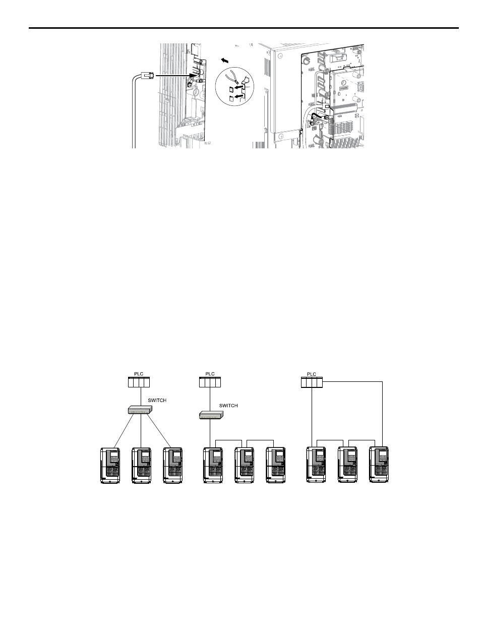
The dual RJ45 network ports on the option board act as a switch to allow for flexibility in cabling topology. For example,
a traditional star network topology may be employed by using a single port on the option board. Alternatively, a daisy-
chained approach may be employed by using both RJ45 ports. The daisy-chained approach reduces the requirements
of central switch ports. A ring topology is also possible.
Yaskawa
Drive
Yaskawa
Drive
Yaskawa
Drive
Yaskawa
Drive
Yaskawa
Drive
Yaskawa
Drive
Yaskawa
Drive
Yaskawa
Drive
Yaskawa
Drive
Star Topology
Daisy-Chained Topology
Ring Topology
Figure 8 Topology Options
5 Installation Procedure
YASKAWA SIEP YAICOM 16A 1000-Series Option Dual-Port EtherNet/IP SI-EN3D Technical Manual
15