Option components, Si-en3d dual-port ethernet/ip option, Communication connector cn1 – Yaskawa SI-EN3D User Manual
Page 9: 4option components, 4 option components
4
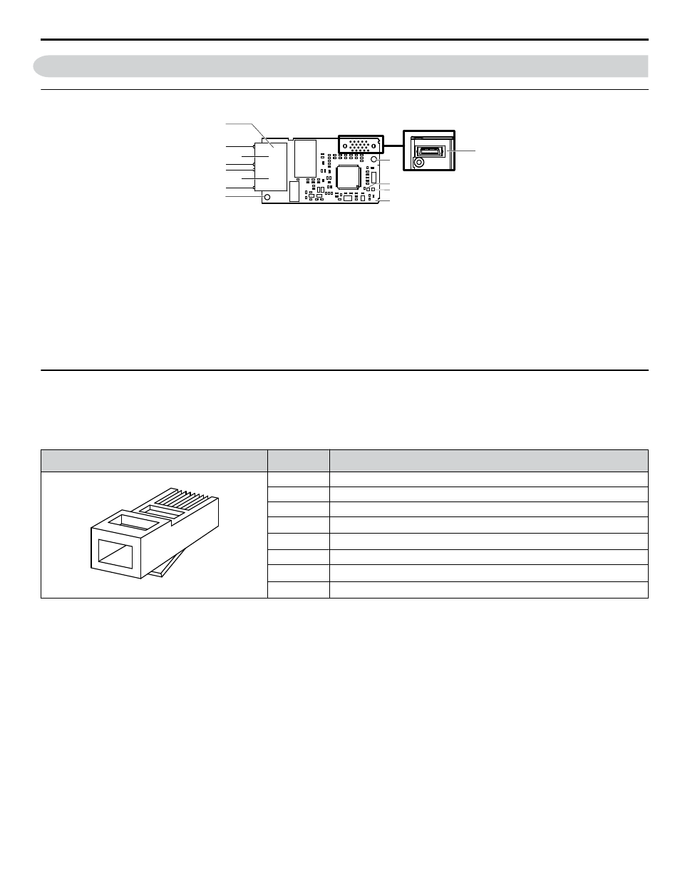
Option Components
u
SI-EN3D Dual-Port EtherNet/IP Option
M
A
I
H
G
E
B
D
F
C
J
K
L
Underside
A – Ground terminal and installation
hole
<1>
B – Port 2 LED (10/100)
<2>
C – Port 2
D – Port 2 LED (LINK/ACT)
<2>
E – Port 1 LED (10/100)
<2>
F – Port 1
G – Port 1 LED (LINK/ACT)
<2>
H – EtherNet/IP cable connector
I – Option connector
J – Installation hole
K – LED (MS)
<2>
L – LED (NS)
<2>
M – EtherNet/IP PCB
Figure 1 Option Components
<1> The ground wire is packaged loose in the option shipping package. Connect this ground wire during installation.
<2>
Refer to Option LED Display on page 10
for details on the LEDs.
u
Communication Connector CN1
The communication connector on the option is a modular RJ45 female connector designated CN1.
CN1 is the connection point for a customer-supplied male Ethernet network communication cable.
Table 2 Male, 8-Way Ethernet Modular Connector (Customer-Supplied)
Male Ethernet 8-Way Modular Connector
Pin
Description
Latch release
1 2 3 4 5 6 7 8
1 (Pair 2)
Transmit data (TXD) +
2 (Pair 2)
Transmit data (TXD) -
3 (Pair 3)
Receive data (RXD) +
4 (Pair 1)
Not used
<1>
5 (Pair 1)
Not used
<1>
6 (Pair 3)
Receive data (RXD) -
7 (Pair 4)
Not used
<1>
8 (Pair 4)
Not used
<1>
<1> Not used for 10 Mbps and 100 Mbps networks.
4 Option Components
YASKAWA SIEP YAICOM 16A 1000-Series Option Dual-Port EtherNet/IP SI-EN3D Technical Manual
9