Main circuit wire gauges and tightening torque – Yaskawa U1000 Industrial MATRIX Drive User Manual
Page 24
n
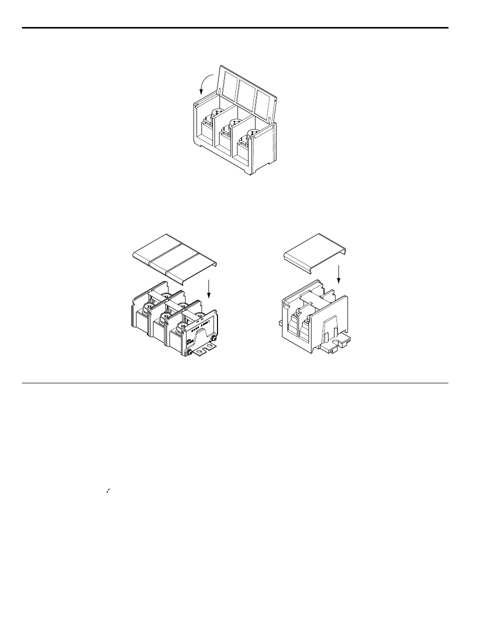
Main Circuit Protective Cover
Close the protective cover after wiring the main circuit terminals on 2o0028 to 2o0081 and 4o0011 to 4o0077.
Figure i.14 Main Circuit Protective Cover (Models 2o0028 to 2o0081 and 4o0011 to 4o0077)
Attach the protective covers after wiring the main circuit terminals and p1, and n1 terminals on models 2o0104 to 2o0248
and 4o0096 to 4o0414.
Main circuit terminal
Terminals p1, n1
Figure i.15 Protective Cover (Models 2o0104 to 2o0248 and 4o0096 to 4o0414)
u
Main Circuit Wire Gauges and Tightening Torque
Use the tables in this section to select the appropriate wires and crimp terminals.
Gauges listed in the tables are for use in the United States.
Note:
Wire gauge recommendations based on drive continuous current ratings (ND) using 75 °C 600 Vac vinyl-sheathed wire assuming ambient
temperature within 40 °C and wiring distance less than 100 m.
Consider the amount of voltage drop when selecting wire gauges. Increase the wire gauge when the voltage drop is greater
than 2% of motor rated voltage. Ensure the wire gauge is suitable for the terminal block. Use the following formula to calculate
the amount of voltage drop:
Line drop voltage (V) = 3 × wire resistance (Ω/km) × wire length (m) × current (A) × 10
-3
Refer to UL Standards Compliance on page 82
for information on UL compliance.
The wire gauges listed in the following tables are Yaskawa recommendations. Refer to local codes for proper wire gauge
selections.
i.4 Electrical Installation
24
YASKAWA ELECTRIC TOEP C710636 04C U1000 Industrial MATRIX Drive Quick Start Guide