Memobus/modbus termination, Terminal dm+ and dm- output signal selection, Enable the internal emc filter – Yaskawa U1000 Industrial MATRIX Drive User Manual
Page 37
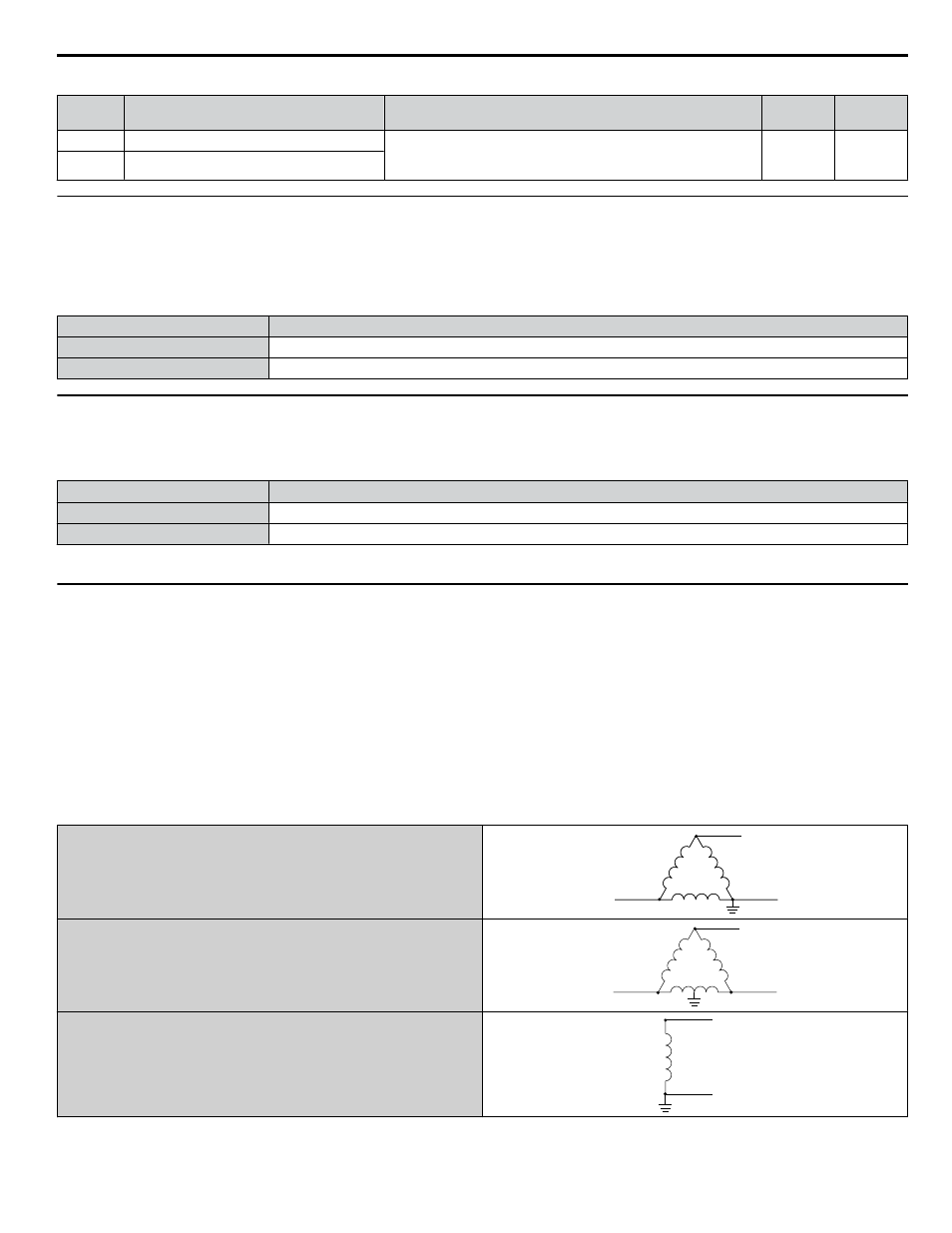
Table i.17 Parameter H4-07 and H4-08 Details
No.
Parameter Name
Description
Setting
Range
Default
Setting
H4-07
Terminal AM signal level selection
0: 0 to 10 Vdc
1: -10 to 10 Vdc
2: 4 to 20 mA
0 to 2
0
H4-08
Terminal FM signal level selection
u
MEMOBUS/Modbus Termination
This drive is equipped with a built-in termination resistor for the RS-422/RS-485 communication port. DIP switch S2 enables
or disabled the termination resistor as shown in
. The OFF position is the default. The termination resistor should
be placed to the ON position when the drive is the last in a series of slave drives.
Table i.18 MEMOBUS/Modbus Switch Settings
S2 Position
Description
ON
Internal termination resistor ON
OFF
Internal termination resistor OFF (default setting)
u
Terminal DM+ and DM- Output Signal Selection
Slide switch S6 selects N.C. or N.O. as the state of the DM+ and DM- terminals for EDM output.
Table i.19 EDM Switch Settings
S2 Position
Description
N.O.
Normally open
N.C.
Normally closed (default setting)
Note:
Refer to Safe Disable Input Function on page 88
for details on EDM.
u
Enable the Internal EMC Filter
DANGER! Electrical Shock Hazard. Do not touch SW screw while power is applied to the drive. Failure to comply will result in death or
serious injury.
WARNING! Electrical Shock Hazard. Connect the ground cable correctly. Failure to comply may result in death or serious injury.
NOTICE: When disabling the internal EMC filter, move the screws from ON to OFF and then tighten to the specified torque. Completely
removing the screws or tightening the screws to an incorrect torque may cause drive failure.
Note:
For floating, impedance grounded, or asymmetrically grounded networks, disconnect the internal EMC filter by moving the SW screw to
the OFF position.
shows asymmetrical grounded networks. Asymmetrical networks require first moving the SW screw to disconnect
the internal ground connection. (Drives are shipped with the SW screw installed at the OFF position.)
Table i.20 Asymmetrical Grounded Network
Grounded at the corner of the delta
L1
L2
L3
Grounded at the middle of the side
L1
L2
L3
Single-phase, grounded at the end point
L1
N
i.4 Electrical Installation
YASKAWA ELECTRIC TOEP C710636 04C U1000 Industrial MATRIX Drive Quick Start Guide
37