Yaskawa U1000 Industrial MATRIX Drive User Manual
Page 55
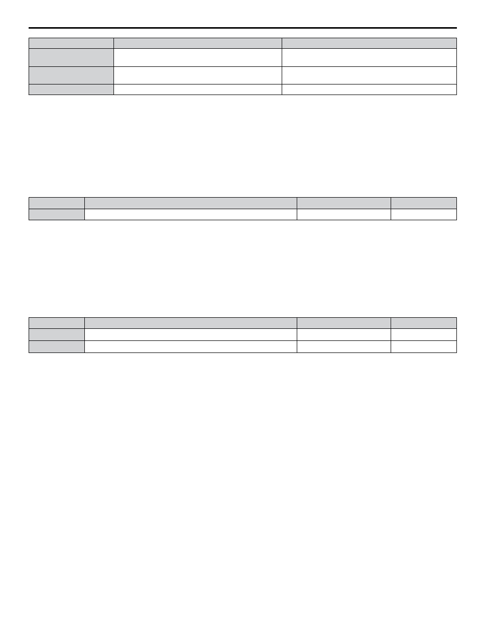
Characteristics
Heavy Duty Rating (HD)
Normal Duty Rating (ND)
Stall Prevention during
Acceleration (L3-02)
150%
120%
Stall Prevention during
Run (L3-06)
150%
120%
Default Carrier Frequency
4 kHz
4 kHz
Note:
Changing the Duty Mode selection automatically changes the maximum size motor that the drive can run, sets the E2-oo parameters to
appropriate values (E4-oo for motor 2), and recalculates parameter settings determined by motor capacity (e.g., b8-04, L2-03, n5-02,
C5-17, and C5-37).
n
C7-60: Output Voltage Limit Mode Selection
Sets the mode to limit the output voltage.
Set this parameter to 0 (Harmonic suppression priority mode) to give priority to harmonic suppression. The maximum output
voltage is automatically limited to suppress harmonics.
Set this parameter to 1 (High output voltage mode) to give priority to the output voltage over harmonic suppression. The
effectiveness of harmonic suppression will be reduced because the maximum output voltage will be used.
No.
Parameter Name
Setting Range
Default
C7-60
Output Voltage Limit Mode Selection
0, 1
1
Setting 0: Harmonic Suppression Priority Mode
Setting 1: High Output Voltage Mode
n
d1-01 to d1-17: Frequency Reference 1 to 16 and Jog Frequency Reference
The drive lets the user switch between up to 17 preset frequency references during run (including the Jog reference) through
the digital input terminals. The drive uses the acceleration and deceleration times that have been selected when switching
between each frequency reference.
The Jog frequency overrides all other frequency references and must be selected by a separate digital input.
The multi-speed references 1, 2, and 3 can be provided by analog inputs.
No.
Parameter Name
Setting Range
Default
d1-01 to d1-16
Frequency Reference 1 to 16
0.00 to 400.00 Hz
<1>
<2>
0.00 Hz
<2>
d1-17
Jog Frequency Reference
0.00 to 400.00 Hz
<1>
<2>
6.00 Hz
<2>
<1> The upper limit is determined by the maximum output frequency (E1-04) and upper limit for the frequency reference (d2-01).
<2> Setting units are determined by parameter o1-03. The default is “Hz” (o1-03 = 0) in V/f, V/f w/PG, OLV, CLV, and OLV/PM control modes. The
default for AOLV/PM and CLV/PM control modes expresses the frequency reference as a percentage (o1-03 = 1).
Multi-Step Speed Selection
To use several speed references for a multi-step speed sequence, set the H1-oo parameters to 3, 4, 5, and 32. To assign the
Jog reference to a digital input, set H1-oo to 6.
Notes on using analog inputs as Multi-Speed 1, 2, and 3:
• Multi-Step Speed 1
Set b1-01 to 1 to set terminal A1 analog input to Multi-Step Speed 1.
Set b1-01 to 0 when setting d1-01, Frequency Reference 1, to Multi-Step Speed 1.
• Multi-Step Speed 2
Set H3-06, Terminal A3 Function Selection, to 2 (Auxiliary Frequency Reference 1) when setting terminal A3 analog input
to Multi-Step Speed 2.
Set H3-06 to F (Through mode) when setting d1-02, Frequency Reference 2, to Multi-Step Speed 2.
• Multi-Step Speed 3
Set H3-10, Terminal A2 Function Selection, to 3 (Auxiliary Frequency Reference 2) when setting terminal A2 analog input
to Multi-Step Speed 3.
Set H3-10 to F (Through mode) when setting d1-03, Frequency Reference 3, to Multi-Step Speed 3.
Set H3-09 to 0 and set DIP switch S1 on the control circuit terminal board to V (voltage) when inputting 0 to 10 V to terminal
A2 analog input.
Select the different speed references as shown in
illustrates the multi-step speed selection.
i.5 Start-Up Programming and Operation
YASKAWA ELECTRIC TOEP C710636 04C U1000 Industrial MATRIX Drive Quick Start Guide
55