B1-03: stopping method selection – Yaskawa U1000 Industrial MATRIX Drive User Manual
Page 50
Setting A1-03 to 3330 initializes the drive and presets terminals S1, S2, and S5 to Start, Stop, and FWD/REV.
Setting 2: MEMOBUS/Modbus Communications
This setting requires entering the Run command via serial communications by connecting the RS-485/RS-422 serial
communication cable to control terminals R+, R-, S+, and S- on the removable terminal block.
Setting 3: Option Card
This setting requires entering the Run command via the communication option board by plugging a communication option
board into the CN5-A port on the control PCB. Refer to the option board manual for instructions on integrating the drive into
the communication system.
Note:
If b1-02 is set to 3, but an option board is not installed in CN5-A, an oPE05 operation error will be displayed on the digital operator and
the drive will not run.
n
b1-03: Stopping Method Selection
Selects how the drive stops the motor when the Run command is removed or when a Stop command is entered.
No.
Parameter Name
Setting Range
Default
b1-03
Stopping Method Selection
0 to 3
<1>
0
<1> The setting range is 0, 1, or 3 in CLV, OLV/PM, AOLV/PM, and CLV/PM.
Setting 0: Ramp to Stop
When the Run command is removed, the drive will decelerate the motor to stop. The deceleration rate is determined by the
active deceleration time. The default deceleration time is set to parameter C1-02.
When the output frequency falls below the level set in parameter b2-01, the drive will start DC injection or Zero Speed Control
depending on the selected control mode. .
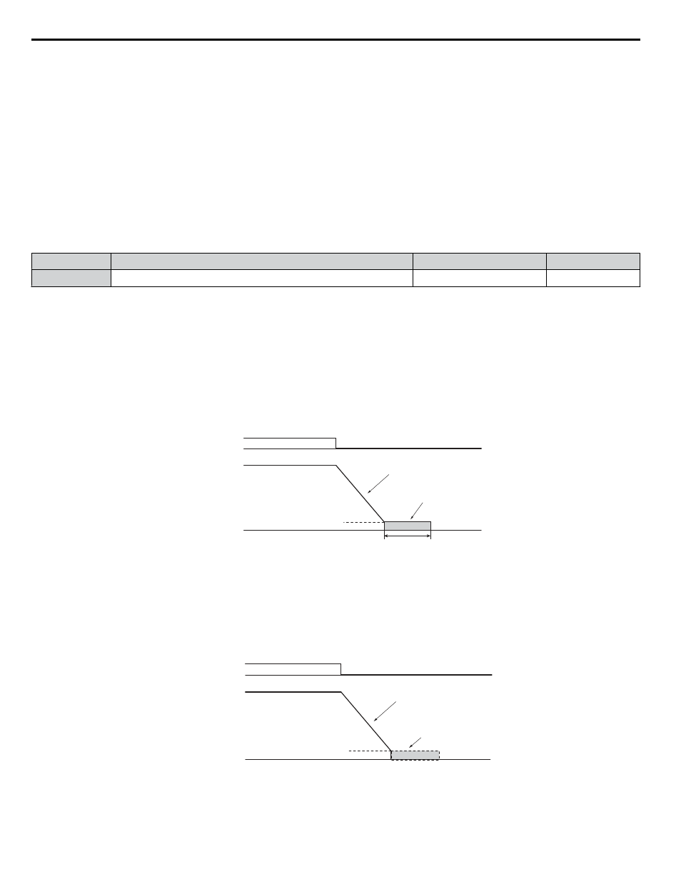
V/f, V/f w/PG and OLV (A1-02 = 0, 1, 2)
For these control modes, parameter b2-01 sets the starting frequency for DC Injection Braking at Stop. When the output
frequency falls below the setting of b2-01, DC Injection Braking is enabled for the time set in parameter b2-04.
Run command
Output frequency
ON
OFF
E1-09 Min. Output Frequency
b2-01 DC Injection Braking Start Frequency
DC Injection Braking
b2-04
Deceleration in the time set
Figure i.34 DC Injection Braking at Stop for V/f, V/f w/PG, and OLV
Note:
If b2-01 is set to a smaller value than E1-09 (Minimum Output Frequency), then DC Injection Braking will begin when the frequency falls
to the E1-09 value.
OLV/PM and AOLV/PM (A1-02 = 5, 6)
When the output frequency falls below the setting of b2-01, drive output is shut down, and DC Injection Braking is performed
for the time set in b2-04.
Run command
Output frequency
ON
OFF
Short Circuit Braking
E1-09 Min. Output Frequency
b2-01 DC Injection Braking Start Frequency
Deceleration in the time set
Figure i.35 Coast to Stop (OLV/PM and AOLV/PM)
Note:
If b2-01 is set to a smaller value than E1-09 (Minimum Output Frequency), then DC Injection Braking will begin when the frequency falls
to the E1-09 value.
i.5 Start-Up Programming and Operation
50
YASKAWA ELECTRIC TOEP C710636 04C U1000 Industrial MATRIX Drive Quick Start Guide