Operator programming errors – Yaskawa U1000 Industrial MATRIX Drive User Manual
Page 72
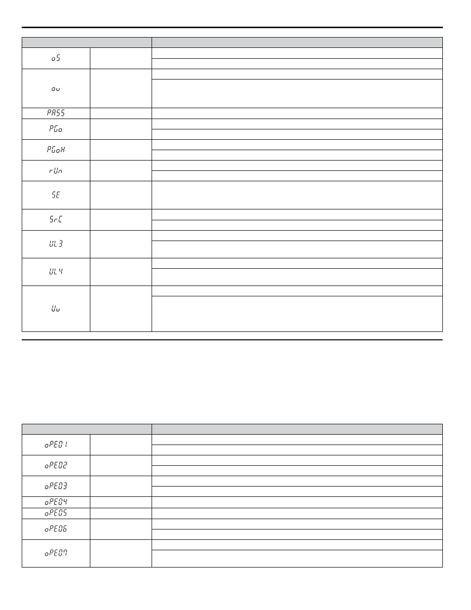
Digital Operator Display
Alarm Name
oS
Overspeed
The motor speed feedback exceeded the F1-08 setting.
ov
Control Circuit Overvoltage
Voltage in the control circuit exceeded the trip point.
• For 200 V class drives: approximately 450 V
• For 400 V class drives: approximately 900 V
PASS
MEMOBUS/Modbus Comm. Test Mode Complete
PGo
PG Disconnect (for any control modes using a PG option card)
No PG pulses are received for longer than the time set to F1-14.
PGoH
PG Hardware Fault (detected when using a PG-X3 option card)
PG cable is not connected properly.
rUn
Motor Switch during Run
A command to switch motors was entered during run.
SE
MEMOBUS/Modbus Communication Test Mode Error
Note:
This alarm will not trigger a multi-function output terminal that is set for alarm output
(H2-oo = 10).
SrC
Phase Order Detection Fault
The phase rotation direction for the input power supply changed.
UL3
Undertorque Detection 1
The current has fallen below the minimum value set for Torque Detection Level 1 (L6-02) for longer than
the allowable time (L6-03).
UL4
Undertorque Detection 2
The current has fallen below the minimum value set for Torque Detection Level 2 (L6-05) for longer than
the allowable time (L6-06).
Uv
Control Circuit Undervoltage
One of the following conditions occurred:
• Contactor to suppress inrush current in the drive was opened.
• Low voltage in the control drive input power. This alarm outputs only if L2-01 is not 0 and DC bus
voltage is under L2-05.
u
Operator Programming Errors
n
oPE Codes
An Operator Programming Error (oPE) occurs when a contradictory parameter is set or an individual parameter is set to an
inappropriate value.
The drive will not operate until the parameter or parameters causing the problem are set correctly. An oPE, however, does not
trigger an alarm or fault output. When an oPE appears on the operator display, press the ENTER button to view U1-18 and
see which parameter is causing the oPE.
Digital Operator Display
Error Name
oPE01
Unit Capacity Setting Fault
Unit capacity and the value set to o2-04 do not match.
oPE02
Parameter Range Setting Error
Use U1-18 to find parameters set outside the range.
oPE03
Multi-Function Input Selection Error
A contradictory setting is assigned to multi-function contact inputs H1-01 to H1-08.
oPE04
Initialization Required
oPE05
Run Command/Frequency Reference Source Selection Error
oPE06
Control Method Selection Error
Correct the setting for the control method.
oPE07
Multi-Function Analog Input Selection Error
A contradictory setting is assigned to multi-function analog inputs H3-02, H3-10, or H3-06 and PID
functions conflict.
i.6 Troubleshooting
72
YASKAWA ELECTRIC TOEP C710636 04C U1000 Industrial MATRIX Drive Quick Start Guide