I.5 start-up programming and operation – Yaskawa U1000 Industrial MATRIX Drive User Manual
Page 51
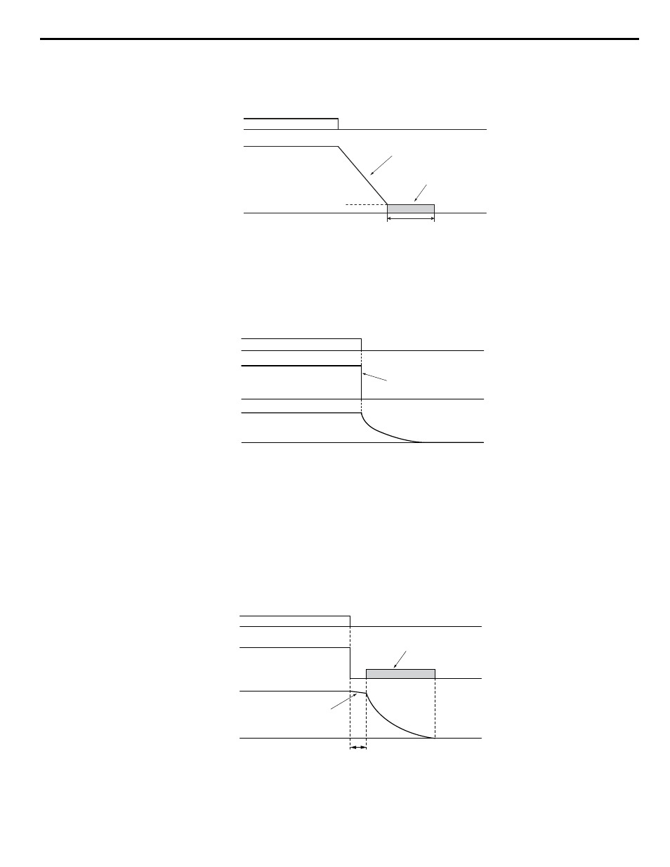
The drive will not perform short-circuit braking when b2-01 = E1-09 = 0 Hz.
CLV and CLV/PM (A1-02 = 3, 7)
For these control modes, parameter b2-01 sets the starting frequency for Zero Speed Control (not position lock) at Stop. When
the output frequency falls below the setting of b2-01, Zero Speed Control is enabled for the time set in parameter b2-04.
Run command
Output frequency
ON
OFF
Zero speed control
b2-04
Deceleration in the time set
E1-09 Min. Output Frequency
b2-01 DC Injection Braking Start Frequency
Figure i.36 Zero Speed Control at Stop in CLV and CLV/PM
Note:
If b2-01 is set to lower than E1-09 (Minimum Output Frequency), then Zero Speed Control begins at the frequency set to E1-09.
Setting 1: Coast to Stop
When the Run command is removed, the drive will shut off its output and the motor will coast (uncontrolled deceleration) to
stop. The stopping time is determined by the inertia and the friction in the driven system.
Drive output is shut off
Run
command
Output
frequency
Motor speed
ON
OFF
Figure i.37 Coast to Stop
Note:
After a stop is initiated, any subsequent Run command entered will be ignored until the momentary power loss minimum baseblock time
(L2-03) has expired. Do not enter Run command until it has come to a complete stop. Use DC Injection at Start or Speed Search to restart
the motor before it has completely stopped.
Setting 2: DC Injection Braking to Stop
When the Run command is removed, the drive will enter baseblock (turn off its output) for the momentary power loss minimum
baseblock time (L2-03). When the minimum baseblock time has expired, the drive will inject the amount DC Injection Braking
is set in parameter b2-02 into the motor windings to brake the motor. The stopping time in DC Injection Braking to Stop is
significantly faster compared to Coast to Stop.
Note:
This function is not available in CLV (A1-02 = 3) or in control modes for PM motors (A1-02 = 5, 6, 7).
Motor coasts
DC Injection Braking
with the current set in
b2-02
Run
command
Output
frequency
ON
OFF
Motor speed
Momentary Power Loss Minimum Baseblock Time (L2-03)
Figure i.38 DC Injection Braking to Stop
i.5 Start-Up Programming and Operation
YASKAWA ELECTRIC TOEP C710636 04C U1000 Industrial MATRIX Drive Quick Start Guide
51