Yaskawa U1000 Industrial MATRIX Drive User Manual
Page 61
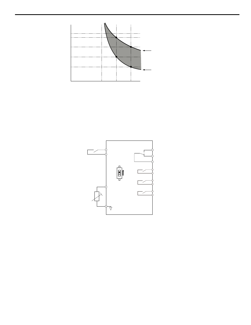
Operation time (minutes)
Cold start
(characteristics when an
overload occurs at a
complete stop)
Hot start
(characteristics when an
overload occurs during
continuous operation at 100%)
Motor current (%)
E2-01 = 100% motor current
10
7
3
1
0.4
0.1
0
100
150
200
Figure i.47 Protection Operation Time for General Purpose Motors at the Rated Output Frequency
n
Motor Protection Using a Positive Temperature Coefficient (PTC) Thermistor
Connect a motor PTC can to an analog input of the drive for motor overheat protection.
The motor overheat alarm level triggers an oH3 alarm and the drive continues the operation selected in L1-03. The overheat
fault level triggers an oH4 fault, outputs a fault signal, and the drive stops the motor using the stop method selected in L1-04.
Connect the PTC between terminals AC and A3 and set jumper S4 on the terminal board to “PTC” as shown in
Set H3-05 to 0 and H3-06 to E.
Drive
Multi-function input
PTC
thermistor
MA
Fault output
Multi-function
digital outputs
MB
MC
A3 (0-10 V)
AC
M1
M2
PTC
AI
DIP Switch S4
M3
M4
M5
M6
Figure i.48 Connection of a Motor PTC
The PTC must exhibit the characteristics shown in
in one motor phase. The motor overload protection of the drive
expects 3 of these PTCs to be connected in a series.
i.5 Start-Up Programming and Operation
YASKAWA ELECTRIC TOEP C710636 04C U1000 Industrial MATRIX Drive Quick Start Guide
61