L1-01: motor overload protection selection – Yaskawa U1000 Industrial MATRIX Drive User Manual
Page 58
n
H2-01 to H2-03: Terminal M1-M2, M3-M4, and M5-M6 Function Selection
No.
Parameter Name
Setting Range
Default
H2-01
Terminal M1-M2 Function Selection (relay)
0 to 192
0: During run
H2-02
Terminal M3-M4 Function Selection (relay)
0 to 192
1: Zero Speed
H2-03
Terminal M5-M6 Function Selection (relay)
0 to 192
2: Speed agree 1
n
L1-01: Motor Overload Protection Selection
The drive has an electronic overload protection function that estimates the motor overload level based on output current, output
frequency, thermal motor characteristics, and time. When the drive detects a motor overload an oL1 fault is triggered and the
drive output shuts off.
L1-01 sets the overload protection function characteristics according to the motor being used.
No.
Name
Setting Range
Default
L1-01
Motor Overload Protection Selection
0 to 6
Determined by
A1-02
Note:
1. When the motor protection function is enabled (L1-01≠ 0), an oL1 alarm can be output through one of the multi-function outputs by
setting H2-01 to 1F. The output closes when the motor overload level reaches 90% of the oL1 detection level.
2. Set L1-01 to a value between 1 and 6 when running a single motor from the drive to select a method to protect the motor from overheat.
An external thermal relay is not necessary.
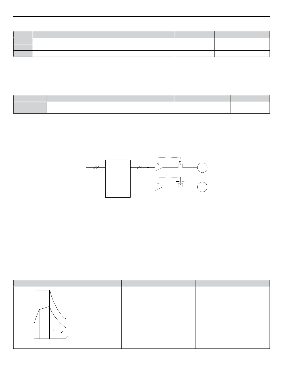
Setting 0: Disabled (Motor Overload Protection Is Not Provided)
Use this setting if no motor overheat protection is desired or if multiple motors are connected to a single drive. If multiple
motors are connected to a single drive, install a thermal relay for each motor as shown in
Drive
Power
supply
M1
MC1
MC1, MC2: Magnetic contactors
L10, L20: Thermal relays
L10
MC2
L20
M2
Figure i.46 Example of Protection Circuit Design for Multiple Motors
NOTICE: Thermal protection cannot be provided when running multi-motors simultaneously with the same drive, or when using motors with
a relatively high current rating compared to other standard motors (such as a submersible motor). Failure to comply could result in motor
damage. Disable the electronic overload protection of the drive (L1-01 = “0: Disabled”) and protect each motor with individual motor thermal
overloads.
Note:
Close MC1 and MC2 before operating the drive. MC1 and MC2 cannot be switched off during run.
Setting 1: General-purpose Motor (Standard Self-cooled)
Because the motor is self-cooled, the overload tolerance drops when the motor speed is lowered. The drive appropriately
adjusts the electrothermal trigger point according to the motor overload characteristics, protecting the motor from overheat
throughout the entire speed range.
Overload Tolerance
Cooling Ability
Overload Characteristics
A: Max. speed for 200LJ and above
B: Max. speed for 160MJ to 180 LJ
C: Max. speed for 132MJ and below
05 33 100 120 167 200
Speed (%)
Continuous
A
B
C
Rated Speed=100% Speed
60 s
150
100
90
60
50
Torque (%)
Motor designed to operate from line
power.
Motor cooling is most effective when
running at rated base frequency (check
the motor nameplate or specifications).
Continuous operation at less than line
power frequency with 100% load can
trigger a motor overload fault (oL1). A
fault is output and the motor will coast
to stop.
i.5 Start-Up Programming and Operation
58
YASKAWA ELECTRIC TOEP C710636 04C U1000 Industrial MATRIX Drive Quick Start Guide