Yaskawa U1000 Industrial MATRIX Drive User Manual
Page 64
WARNING! Sudden Movement Hazard. Ensure start/stop and safety circuits are wired properly and in the correct state before energizing
the drive. Failure to comply could result in death or serious injury from moving equipment. When programmed for 3-Wire control, a momentary
closure on terminal S1 may cause the drive to start.
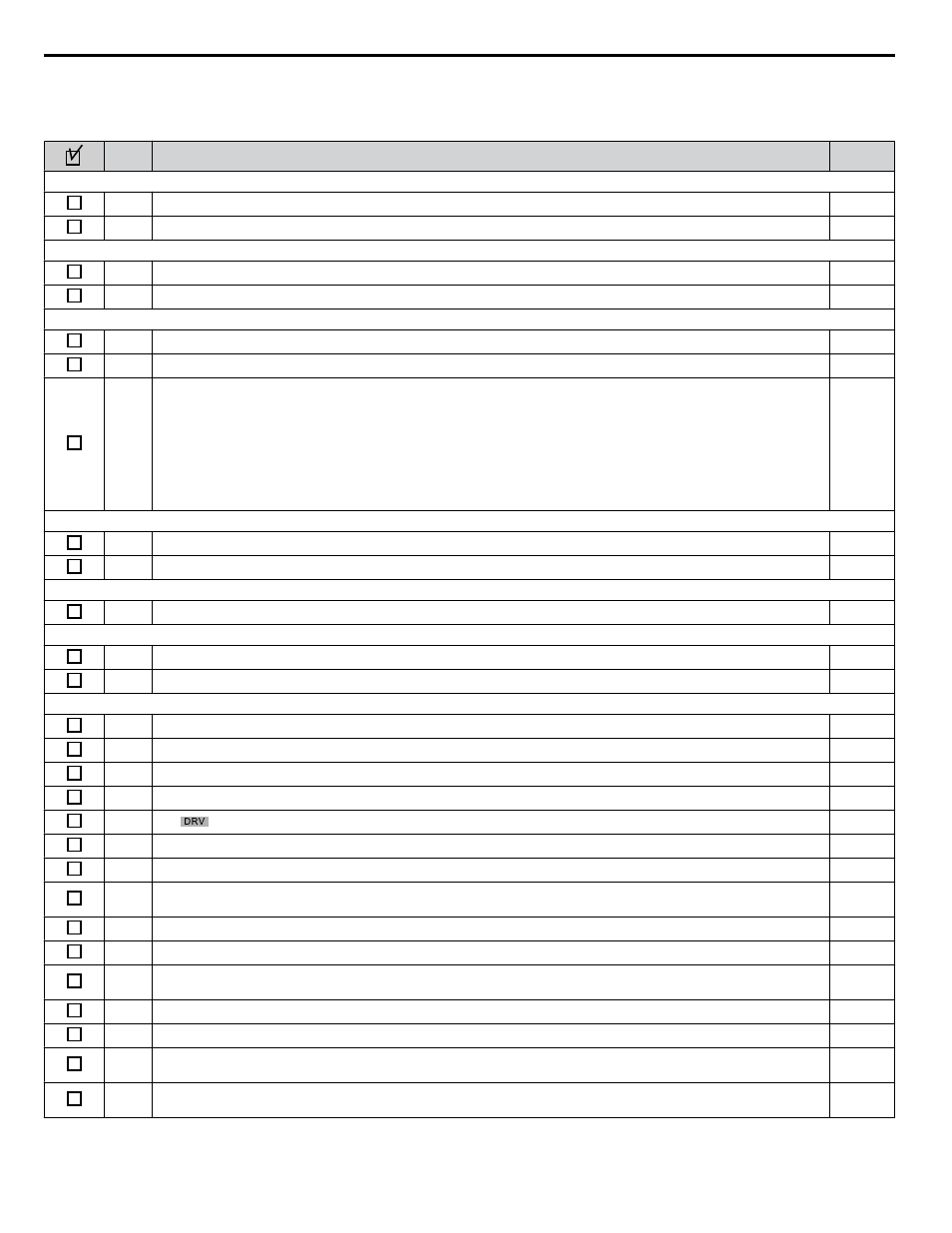
No.
Checklist
Page
V/f Control (A1-02 = 0) and V/f Control with PG (A1-02 = 1)
3
Select the best V/f pattern according to the application and motor characteristics.
–
4
Perform Rotational Auto-Tuning for V/f Control if using Energy Saving functions.
–
V/f Control with PG (A1-02 = 1)
5
Set up the PG feedback parameters correctly and make sure the encoder pulse counting direction is correct.
–
6
Set the proportional gain for ASR speed control to C5-01 and the integral time to C5-02.
–
Open Loop Vector Control (A1-02 = 2) or Closed Loop Vector Control (A1-02 = 3)
7
Decouple motor shafts and machines when performing Rotational Auto-Tuning.
–
8
Set the Auto-Tuning mode to T1-01 (0 for Rotational Auto-Tuning).
–
9
Enter the following data according to the information listed on the motor nameplate:
• Motor rated power to T1-02 (kW)
• Motor rated voltage to T1-03 (V)
• Motor rated current to T1-04 (A)
• Motor base frequency to T1-05 (Hz)
• Number of motor poles to T1-06
• Motor base speed to T1-07 (r/min)
–
Closed Loop Vector Control (A1-02 = 3)
10
Set F1-01 and F1-05.
–
11
Set ASR proportional gain to C5-01 and ASR integral time to C5-02. Perform ASR Tuning if possible.
–
Open Loop Vector Control for PM (A1-02 = 5)
12
Perform Auto-Tuning as described.
–
Advanced Open Loop Vector Control for PM (A1-02 = 6)
13
Perform Auto-Tuning as described.
–
14
Set the proportional gain for ASR speed control to C5-01 and the integral time to C5-02.
–
Closed Loop Vector Control for PM (A1-02 = 7)
15
Set PM motor data using E5-oo parameters.
–
16
Set ASR proportional gain to C5-01 and ASR integral time to C5-02. Perform ASR Tuning if possible.
–
17
Set F1-01 and F1-05.
–
18
Set the offset between the rotor magnetic axis and the Z-pulse of the connected encoder to E5-11.
–
19
The
should be displayed on the LCD operator after giving a Run command.
–
20
To give Run command and frequency reference from the digital operator, press “LO/RE” key to set to LOCAL.
–
21
If the motor rotates in the opposite direction during test run, switch two of U/T1, V/T2, W/T3, or change b1-14.
–
22
In accordance with load condition, set Heavy Duty or Normal Duty mode using parameter C6-01. Normal Duty is the
default setting.
–
23
Set motor rated current (E2-01, E4-01, E5-03) and motor protection (L1-01) values for motor thermal protection.
–
24
Set the drive for REMOTE when control circuit terminals provide the Run command and frequency reference.
–
25
If the control circuit terminals should supply the frequency reference, select the correct voltage input signal level
(0 to 10 V or -10 to +10 V) or the correct current input signal level (4 to 20 mA or 0 to 20 mA).
26
Apply the proper signal level to terminals A1 and A3 (0 to 10 V or -10 to +10 V).
–
27
Apply the proper signal level (-10 to +10 V, 4 to 20 mA or 0 to 20 mA) to terminal A2.
–
28
When current input is used, switch the built-in DIP switch S1 from the V-side to I-side. Set the level for current signal
used to H3-09 (set “2” for 4 to 20 mA, or “3” for 0 to 20 mA).
–
29
Set DIP Switch S1 on the drive to “I” when using terminal A2 as current input.
Set DIP Switch S1 on the drive to “V” when using terminal A2 as voltage input.
–
i.5 Start-Up Programming and Operation
64
YASKAWA ELECTRIC TOEP C710636 04C U1000 Industrial MATRIX Drive Quick Start Guide