Saving parameters, Additional explanation of i/o allocation settings, Master i/o allocations example – Yaskawa 260IF DeviceNet System User Manual
Page 46
4.3 260IF Module Setup
4-13
4
Saving Parameters
Once the parameters have been set, select File and then Save from the menu to save the set-
tings.
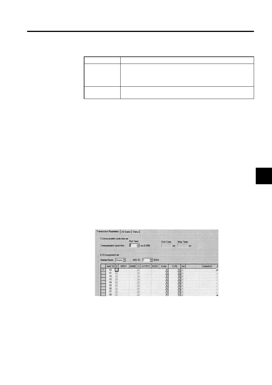
Additional Explanation of I/O Allocation Settings
1. Master/Slave
Set the same value as that set on SW1 (X1) on the 260IF Module.
2. MAC ID
Set the same value as that set on SW2 and SW3 on the 260IF Module.
3. Communications Cycle Time
Enter the communications cycle time calculated in 4.2 Calculating Communications
Cycle Times.
This setting is not required when the 260IF Module is used as a DeviceNet Slave.
4. I/O Allocations
Allocate the I/O registers for data exchange between the Controller CPU and the 260IF
Module according to the DeviceNet system configuration.
Master I/O Allocations Example
The settings in the following diagram are made when, for example, the 260IF Module is to
be used as the DeviceNet Master with MAC ID = 5 and I/O data is to be exchanged
between the 260IF Module and a 2-byte Output Module with MAC ID = 2 and a 1-byte
Input Module with MAC ID = 3.
Setting
Contents
EM
(
Explicit
Message)
EM is turned ON when the 260IF Module is set as a DeviceNet Master and
only message communications are performed with Slaves.
The EM allocation setting is not required when the 260IF Module is set as a
DeviceNet Slave.
Comment
The name and type of the relevant device and other information can be entered
as a character string of up to 32 characters.