1 wiring communications power supply, 1 basic precautions, 2 wiring power supply – Yaskawa 260IF DeviceNet System User Manual
Page 75: Nodes on both sides of the power supply
Wiring
7.1.1 Basic Precautions
7-2
7
7.1 Wiring Communications Power Supply
This section describes wiring methods for communications power supply and calculation meth-
ods for power supply positioning.
7.1.1 Basic Precautions
• The communications power supply to the network must be 24 VDC.
• The communications power supply must have a sufficient margin in the capacity.
• Connect the communications power supply to the trunk line.
• If many nodes are provided with power from a single power supply, locate the power
supply as close as possible to the middle of the trunk line.
• The allowable current flow in a thick cable is 8 A and that in a thin cable is 3 A.
• The power supply capacity for a drop line varies with the drop line length. The longer
a drop line is, the lower the maximum current capacity of the drop line will be regard-
less of the thickness of the drop line. Obtain the allowable current (I) of the drop line
(i.e., the allowable current consumption of the drop line and devices connected to it)
from the following equation.
I = 4.57/L I: Allowable current (A)
L: Drop line length (m)
• If only the communications power supply is turned OFF while the network is operat-
ing, errors may occur in the nodes that are communicating at that time.
7.1.2 Wiring Power Supply
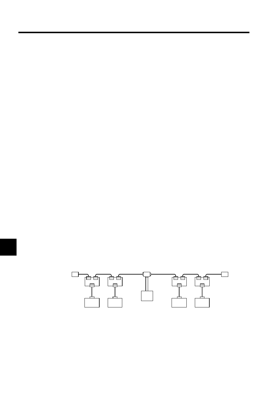
The following diagrams show two layouts for power supply wiring.
Nodes on Both Sides of the Power Supply
Note: The "Nodes on Both Sides of the Power Supply" method is recom-
mended if a single power supply is connected to many nodes.
Power Supply Tap or
T-branch Adapter
Node
Node
Node
Node
Communications
power supply