Slave i/o allocation example – Yaskawa 260IF DeviceNet System User Manual
Page 47
System Startup and Setup
4.3.2 Setting Methods
4-14
4
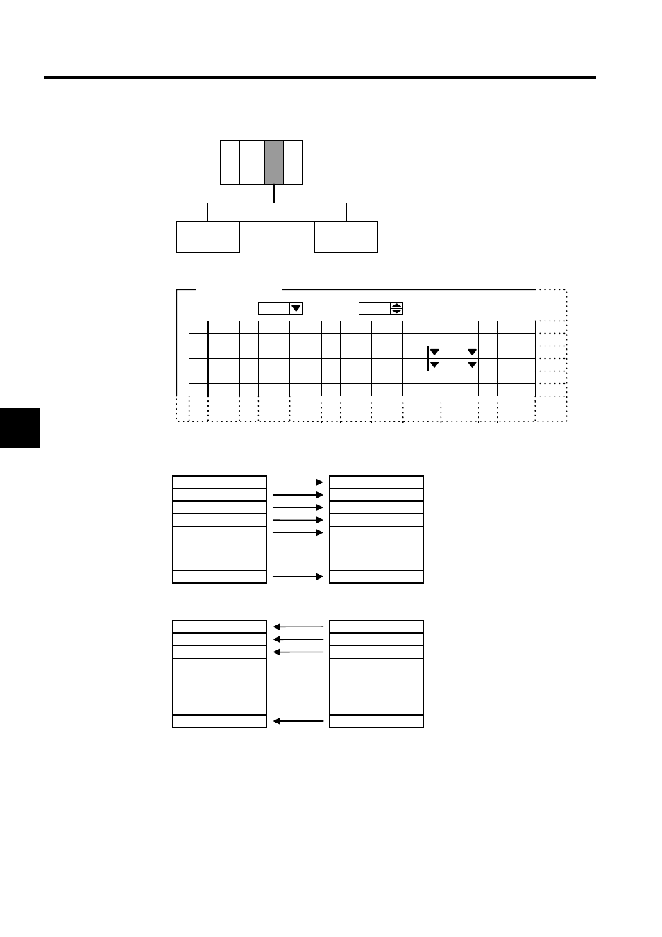
Slave I/O Allocation Example
The settings shown in the following diagram are made when, for example, the 260IF Module
is to be used as a DeviceNet Slave with MAC ID = 3 and input and output sizes of 64 bytes
each and I/O data is to be exchanged with the DeviceNet Master.
Node address #05
(MACID = 05)
Node address
#02
Node address
#03
MACID=02
MAC ID=02
PS
D
SCAN
01
MAC ID
02
03
04
D
INPUT
IW1101
OUTPUT
OW1100
BSIZE
2
Low
TYPE
Polled
EM
BSIZE
1
Low
Polled
01
02
03
04
IW1101
OW1100
2
Low
Polled
1
Low
Polled
Master/Slave
Master
Comments
MAC ID
MAC
OUTPUT
RSIZE
D
SCAN
TYPE
INPUT
RSIZE
FM
5
01
02
03
04
IW1102
Low
Low
Polled
Polled
1
OW1100
2
2. I/O Assignment set
MP920 260IF
D
・
・
・
(
MAC ID = 03 )
IB11021
IB11022
IB11023
IB11024
IB11025
・
・
・
IB110028
・
・
・
(
MAC ID = 05 )
・
・
・
(
MAC ID = 02 )
・
・
・
OB11000
OB11001
OB11002
・
・
・
OB1100F
Node address #03
Node address #05
Input contact signal 1
Input contact signal 2
Input contact signal 3
Input contact signal 4
Input contact signal 5
Input contact signal 8
Input relay
Node address #02
Output contact signal 1
Output contact signal 2
Output contact signal 3
Output contact signal 16
Output coil
IB11020
IB11021
IB11022
IB11023
IB11024
IB11027