Installation, Electrician 7.6.4.1 solar sensor – KACO Powador XP200-HV TL User Manual
Page 33
Installation
Operating Instructions Powador XP200-HV TL, XP250-HV TL, XP350-HV TL_EN
Page 33
Electrician
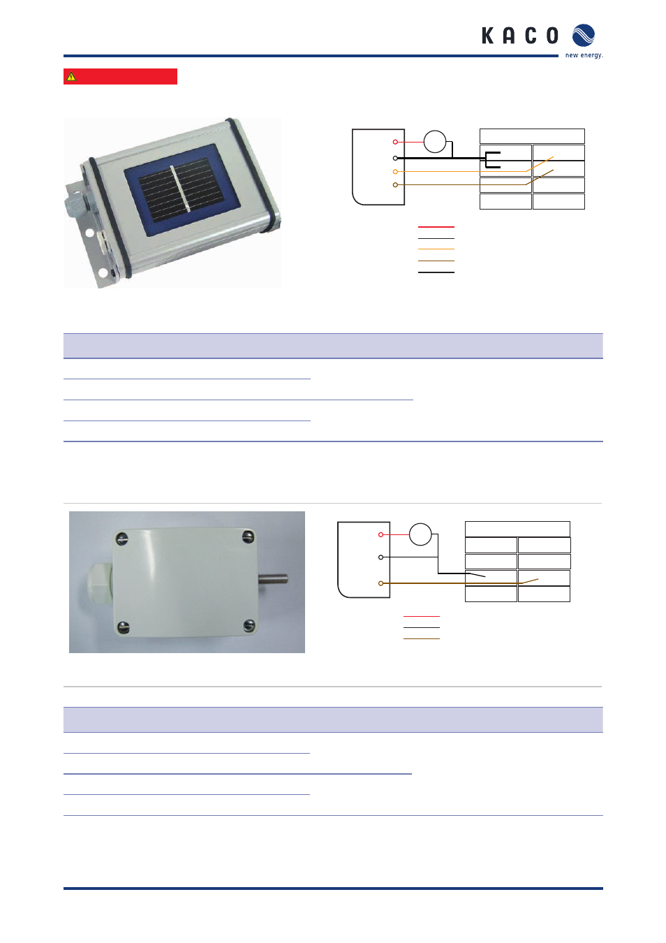
7.6.4.1 Solar sensor
1b
1a
UAI
2a
2b
3a
3b
4a
4b
Si-12TC
bk-t
og
bn
Red (rd)
Black (bk)
Orange (og)
Brown (bn)
Black,
thick cable (bk-T)
VCC (12 V to 24 V)
GND
Insolation (0 ... 10 V)
Solar cell temperature (0 ... 10 V)
GND (housing)
12 ... 24 V
+ -
rd
Figure 31: Si-12TC solar sensor
Figure 32: Connection diagram for solar sensor
Terminal number
Terminal designation
Specification
Wire cross- section, max.
1a
IRN
0 ... 10 V DC
AWG 20
(0.75 mm
2
)
1b
IRP
2a
CTN
0 ... 10 V DC
2b
CTP
Table 13: Connections for analogue user input – solar sensor
7.6.4.2 PT 1000
1b
1a
UAI
2a
2b
3a
3b
4a
4b
PT1000
bk
bn
Red (rd)
Black (bk)
Brown (bn)
VCC (15 V to 24 V)
GND
Temperature (0 to 10 V)
15 V ... 24 V
+ -
rd
Figure 33: PT 1000
Figure 34: Wiring of the PT 1000
Terminal number
Terminal designation
Specification
Wire cross- section, max.
3a
PTN
0 ... 10 V DC
AWG 20
(0.75 mm
2
)
3b
PTP
4a
RSVN
Reserve
4b
RSVP
Table 14: Connections for analogue user input – PT 1000