3 components inside the inverter, Components inside the inverter – KACO Powador XP200-HV TL User Manual
Page 9
Unit description
Operating Instructions Powador XP200-HV TL, XP250-HV TL, XP350-HV TL_EN
Page 9
3.3
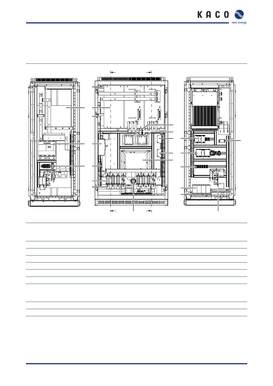
Components inside the inverter
The inverter components are installed inside two cabinets.
Components inside the left cabinet
17
15
14
13
12
11
7
6
4
3
2
1
8
5
10
9
A
A
B
B
A–A
B–B
16
5
Figure 4: Components inside the left cabinet (XP200-HV)
Key
1
24 V voltage supply EMC filter for the MMI
10
DC overvoltage protection
2
Grounding bar
11
DC connection (left side DC+, right side DC–)
3
Ground fault detection
12
DC fuses (number of fuses depends on inverter type)
4
PSIM (master control for interfaces)
13
Terminals for user connector
5
24 V voltage supply
14
DC disconnector
6
Control system (XCU)
15
DC current measurement
7
Fuse protection for voltage supply and
measuring equipment; overvoltage protection
for the voltage supply for the controller
16
PEBB (IGBT block)
8
Auxiliary transformer
17
Door sensor
9
FRT components