2 overview circuit diagram, Overview circuit diagram, Unit description – KACO Powador XP200-HV TL User Manual
Page 8
Advertising
Unit description
Page 8
Operating Instructions Powador XP200-HV TL, XP250-HV TL, XP350-HV TL_EN
3.2
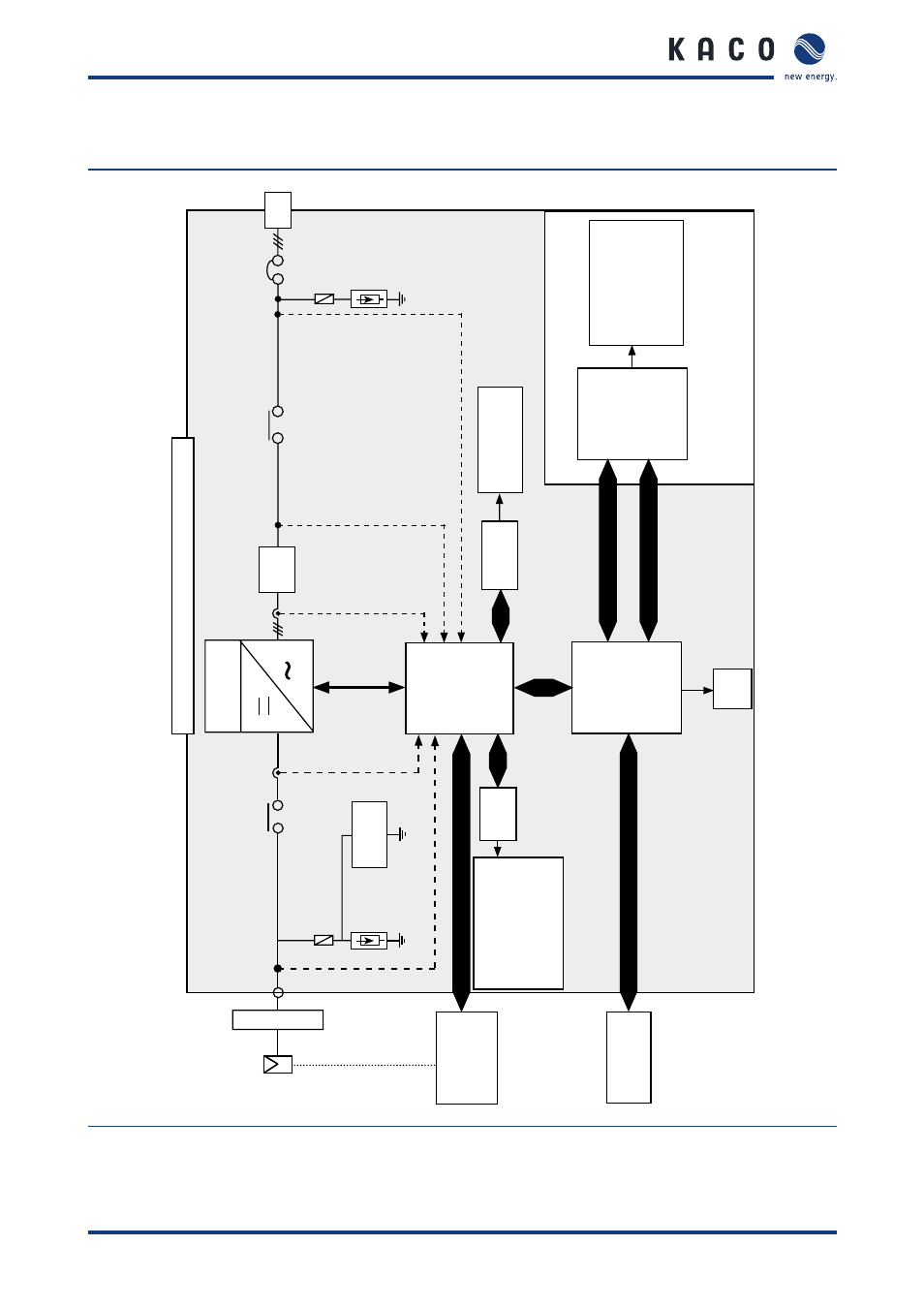
Overview circuit diagram
PV
Mo
dules
450 ... 830 V DC
Inverte
r
Central Inverter
XP
20
0-
HV
TL
/
XP
25
0-
HV
TL /
XP
35
0-
HV
TL
PV
M
(M
od
ul
e
Monitoring
Monitorin
g
RS48
5
US
B
AN
I
Monitorin
g
Subs
ys
tem
Commissioning an
d
Main
tenance
To
ol
(C
MT
)
Parameter Settin
g
Trace
St
atus
Monitoring
MM
I
Subs
ys
te
m
Control
Subsystem
SD
card
Te
mperatur
e
Irradatio
n
Reference cell
et
c.
Etherne
t
LC
Filter
L
12
3
DI
O
Surge
Protector
C
B10
MC
21
Isol
atio
n
Monitoring
S0
-I
nput
(1
Channel)
S0
-O
utput
(1
Chan
nel)
Digital
Input
(1
Cha
nnel
)
Digital
O
utput
(1
Cha
nnel
)
Surge
Protector
CB20
CA
N
or
RS48
5
RS232
V
g,
ab
c
V
C,abc
I
inv,abc
I
dc
V
pv
Figure 3: Configuration of the Powador XP200-HV TL / XP250-HV TL / XP350-HV TL
Advertising
This manual is related to the following products: