Pos-phy interface –5, Pos-phy interface – Altera POS-PHY Level 2 and 3 Compiler User Manual
Page 33
Chapter 3: Functional Description
3–5
Internal Architecture
© November 2009
Altera Corporation
POS-PHY Level 2 and 3 Compiler User Guide
Preliminary
Each MegaCore function includes a separate receiver and transmitter, which can be
instantiated in a single device or separate devices.
There are many similarities in the internal architecture of these blocks. The main
difference is in the non-symmetrical handshaking on the physical interface between
receive and transmit directions.
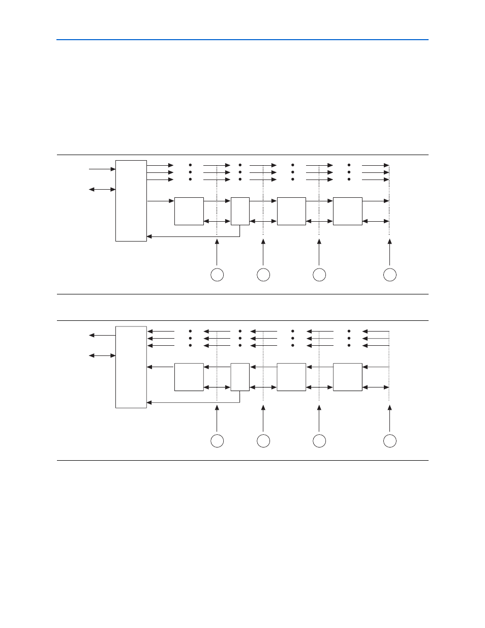
Figure 3–9 on page 3–5
shows the sink MegaCore function block diagram.
Figure 3–10
on page 3–5
shows the source MegaCore function block diagram.
POS-PHY Interface
Each POS-PHY supports single and multi-PHY implementations. The POS-PHY
interface interfaces to an internal multiplexer, which allows access to multiple/single
internal packet FIFO buffers. Status information from the FIFO buffers is used to
control the POS-PHY interface. The source interface provides polled or direct packet
available modes.
Figure 3–9. Sink MegaCore Function Block Diagram
Figure 3–10. Source MegaCore Function Block Diagram
Link-layer or
PHY-Layer
Sink
Interface
Packet
FIFO
Packet Data
Width
Conversion
(wider)
Packet Data
Width
Conversion
(narrower)
Port
N
Port 2
Port 1
Port 0
'B' Interface Options
Control
Data
1
2
3
Control
Link-layer or
PHY-Layer
Source
Interface
Data
4
Link-Layer or
PHY-Layer
Source
Interface
Packet
FIFO
Packet Data
Width
Conversion
(narrower)
Multiplexer
Packet Data
Width
Conversion
(wider)
Port N
Port 2
Port 1
Port 0
'B' Interface Options
Control
Data
1
2
3
Control
Link-layer or
PHY-Layer
Sink
Interface
Data
4