Pos-phy level 2 interface, Pos-phy level 2 interface –22 – Altera POS-PHY Level 2 and 3 Compiler User Manual
Page 50
3–22
Chapter 3: Functional Description
Interface Signals
POS-PHY Level 2 and 3 Compiler User Guide
© November 2009
Altera Corporation
Preliminary
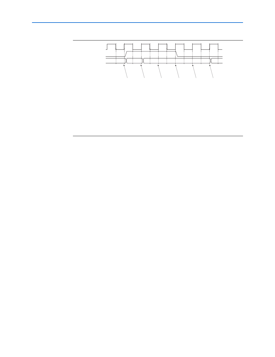
According to the POS-PHY specifications, when renb is sampled low by the PHY
device, a read is performed from the receive FIFO buffer and the rdat[31:0] signals
are updated on the following rising edge of rfclk.
POS-PHY Level 2 Interface
The interface direction is shown as either link to PHY, or PHY to link.
For a POS-PHY level 2 link-layer MegaCore function, the following applies:
■
Link to PHY results in an output port on the MegaCore function.
■
PHY to link results in an input port on the MegaCore function.
For a POS-PHY level 2 PHY-layer MegaCore function, the following applies:
■
Link to PHY results in an input port on the MegaCore function.
■
PHY to link results in an output port on the MegaCore function.
1
‘A’ interface signals are prefixed by a_; ‘B’ interface signals are prefixed by b1_, b2_,
and so on.
Table 3–11
describes the POS-PHY level 2 transmit interface.
Figure 3–16. The renb Signal Behavior
Notes to
Figure 3–16
:
(1) The renb signal is sampled low—another read may take place.
(2) The renb signal is sampled high—all signals must stabilize and remain unchanged on the following
rfclk
rising edge.
(3) The renb signal was sampled high on the previous rfclk rising edge—all signals must remain
unchanged. The MegaCore function uses this time to sample data from rdat[31:0]. The POS-PHY
specification allows data to be sampled anytime between 3 and 6 (3, 4, 5, or 6 are all valid).
(4) The renb signal remains high—all signals must remain unchanged.
(5) The renb signal is sampled low, therefore data may change on the next rfclk rising edge.
(6) Data on rdat[31:0] and all other signals may change.
renb
rfclk
rdat[31:0]
(1)
(2)
(3)
(4)
(5)
(6)