6 8019 and 8020 combined remote start – Cadac F-Type User Manual
Page 15
Connecting the mixer systems
1-7
Revision F2005-2
F-Type
41619
;34<#DQG#;353#FRPELQHG#5HPRWH#VWDUW
Each 8019 and 8020 switch-mode power supply is fitted with a front panel mounted 9
way ‘D-type’ connector. This connecto r is labelled “Connections for Remote Start”.
You may connect a single remote start switch to each unit, have one switch start a
“system” pair, or wire up a single switch to start “system 1” and “system 2” all at the
same time.
Fig 1-5 applies to 8019 and 8020 PSUs up to serial number 34949 and shows the
circuit for starting up a “system” pair with a single switch. This has proved to be the
most popular method of connecting the remote start facility. This circuit can easily be
extended to provide a single switch remote for all four PSUs if required.
For 8019 and 8020 PSUs from serial number 34950 onwards, see fig 1-6 and 1-7.
NOTE:
■
■
■
■
The remote must be a ‘momentary’ type. You will need a two-pole switch for a
single PSU, a four-pole switch for a “system” pair, or a six-pole switch for controlling
all four units.
■
■
■
■
The remote switch(es) must be mounted on a metal panel.
■
■
■
■
Use shielded cable for the remote switch wiring.
■
■
■
■
The 9-way ‘D-type’ free plug must have a conductive shell. This is to ensure that
the cable shield connects directly to the PSU unit chassis.
■
■
■
■
Connect the cable shield to the metal panel where the remote start switch(es)
are mounted.
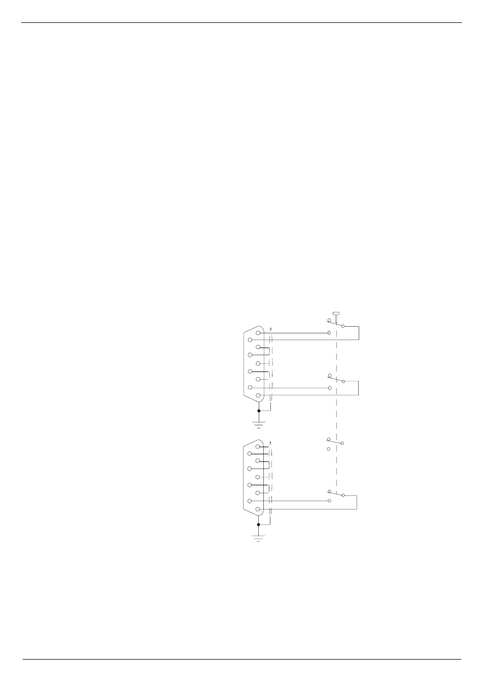
Great care must be taken with the wiring of the switch(es) to ensure that no short-cir-
cuits can occur between any two power supply units.
FIG 1-7. Remote start of 8019/8020 up to serial number 34950
PANEL MOUNTED 4-POLE
VIEW FROM SOLDER
CUP/TAG SIDE
5
9
4
8
3
2
6
1
7
5
9
4
8
3
2
6
1
7
MOMENTARY SWITCH
TO CONNECTION
FOR REMOTE START
ON 8019 FRONT PANEL
TO CONNECTION
FOR REMOTE START
ON 8020 FRONT PANEL
NOTE: CABLE SCREEN IS
CONNECTED AT BOTH ENDS