2 ccm rear panel connectors, See fig 2-3), 515 &&0#uhdu#sdqho#frqqhfwruv – Cadac F-Type User Manual
Page 34
2-6
Central Control Module 7896
F-Type
Revision F2005-2
515
&&0#UHDU#SDQHO#FRQQHFWRUV
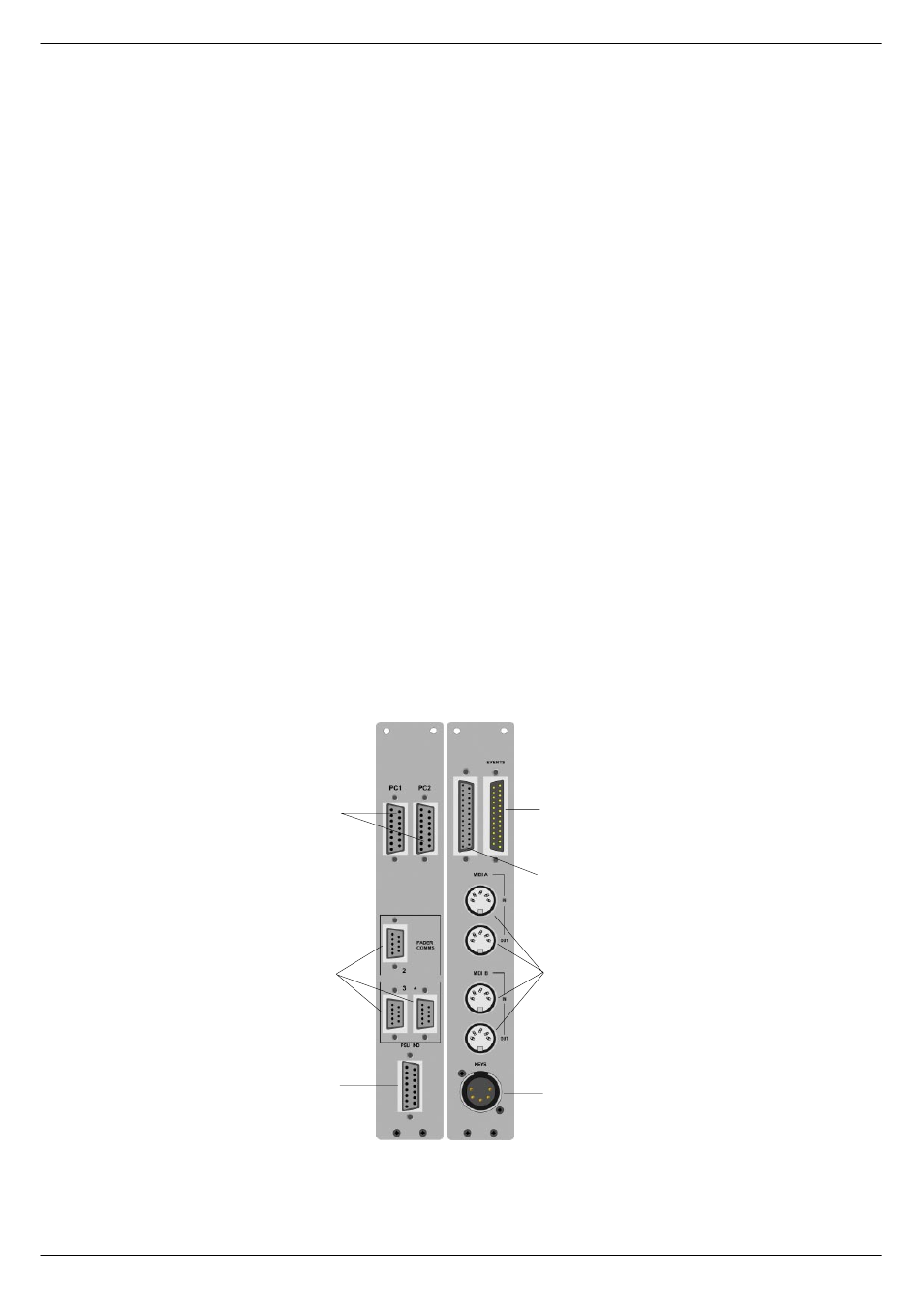
Please refer to figure 2-3 for the location of the connectors on the F-Type CCM mod-
ule rear panel described below.
+D,
)DVW#&RSSHU#&RPPXQLFDWLRQV#,22
Two cables provide the “fast copper” data link between the CCM and up to two IBM®
PC or compatible computers if these are fitted with a CADAC Fast Copper Communi-
cations board 7514. Otherwise the cables run between the CCM and the Séance
box, see
and
. Two cables are
normally supplied, one for PC1 and the other for PC2. The connectors are labelled
differently at each end. Make sure that the “CONNECT TO CCM” end is connected
to the CCM! The other ends of the cables are labelled “PC1” and “PC2” respectively
If the cables are not connected correctly, the communications system cannot work.
+E,# 368#,QGLFDWRUV
A cable with a 15 way 'D-Type' male connector at one end to a 15 way 'D-Type'
female connector at the other end is supplied for interconnection between the
PSU
Indicators male connector on the CCM and the PSU Indicators female connector on
the console frame.
The
PSU System 1 and PSU System 2 LEDs on the CCM front panel (e) in fig 2-1)
will not work unless this connection is made.
+F,
5HPRWH#&RQWURO#
The 25 way female 'D-Type' connector labelled
RC, is for use with the eight “STOP”
and “START” switches mounted near the top of the front panel (c) in figure 1.11).
Unless special instructions are received from the customer, this connector is not
FIG 2-3. F-Type CCM rear panel
D
E
F
G
H
I
J