Cadac F-Type User Manual
Page 35
Central Control Module 7896
2-7
Revision F2005-2
F-Type
wired directly to the “STOP” and “START” switches, but terminates in a 25 way IDC-
connector. This allows the user to configure the switch wiring to suit the equipment
they are intended to control. Great care must betaken with the wiring of the
switch(es) to ensure that no short-circuits can occur between any two power supply
units.
+G,
0,',#LQSXWV#DQG#RXWSXWV
Four 5 pin DIN, standard MIDI connectors for the two banks A and B are included.
The outputs may be connected to any MIDI compatible outboard equipment that
responds to program changes, note on/ note off and velocity information. See Sound
Automation Manager or SAM manual - MIDI, for programming details.
+H,
.H\V
See
and
1.5.14 Using the Video and Keyboard Change over func-
.
+I,
)DGHU#FRPPXQLFDWLRQV
See
1.4.1 Audio Bus / Data Bus Connections
, chapter 1.
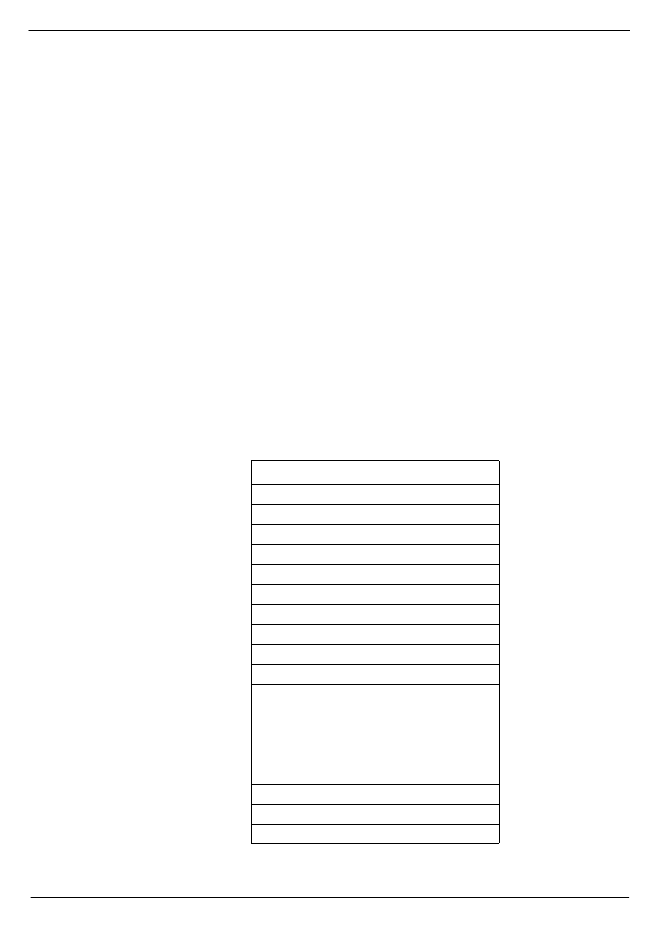
+J,# (YHQWV
The 25 way male 'D-Type' connector labelled
EVENTS allows the EVENT relay con-
tacts to be wired out for external equipment control. The wiring details are shown in
Table 1. See SAM manual for details.
Pin no.
Relay no.
Function
01
1
normally CLOSED contact
14
1
MOVING contact (wiper)
02
1
normally OPEN contact
15
2
normally CLOSED contact
03
2
MOVING contact (wiper)
16
2
normally OPEN contact
04
3
normally CLOSED contact
17
3
MOVING contact (wiper)
05
3
normally OPEN contact
18
4
normally CLOSED contact
06
4
MOVING contact (wiper)
19
4
normally OPEN contact
07
5
normally CLOSED contact
20
5
MOVING contact (wiper)
08
5
normally OPEN contact
21
6
normally closed contact
09
6
MOVING contact (wiper)
22
6
normally OPEN contact