6 earth, 0v and frame connections – Cadac F-Type User Manual
Page 21
Connecting the mixer systems
1-13
Revision F2005-2
F-Type
■
■
■
■
Connect one end of the “PSU IND” cable to the “PSU IND” 15-way male D-sub
connector on the CCM.
■
■
■
■
Connect the other end of the “PSU IND” cable to the “PSU IND” 15-way female
D-sub connector on the rear console frame adjacent to the two multi-pin power input
connectors.
41719
(DUWK/#39#DQG#)UDPH#&RQQHFWLRQV
Figure 1-6 shows the rear panels of the power supply units in a single PSU system.
Under normal conditions, the 0V and Mains-Earth terminals can be connected on
both PSU systems. However, if the a.c. input lines to each pair of PSU’s has a differ-
ent length, you may find that the 0V and Mains-Earth terminals can only be linked on
one set of power supplies, for minimum system noise.
The 0V or FRAME terminals on a PSU need
not be directly connected to the 0V and/
or FRAME connections on console frames. The shielded power supply cables are
connected to the frame at both ends.
In addition to the terminals on the back of the PSUs, there are
0V and FRAME con-
nections on the rear of each console frame. The shorting-bar link between the 0V
and “FRAME” terminals on each frame must be connected. For minimum noise, the
large diameter ‘frame-link’ cables (supplied with multi-frame consoles), must be con-
nected. Always make sure that ‘frame-link’ cable nuts are tightened against the cop-
per bar.
The 0V and FRAME terminals are linked in the factory with a copper bar. This bar
should never be removed when the console is in normal use. Note that
Phantom
Power cannot be delivered from the input modules to the 48V bus if the copper bar is
missing, because the screened microphone input cables will not be terminated. It will
also cause damage to the motor faders.
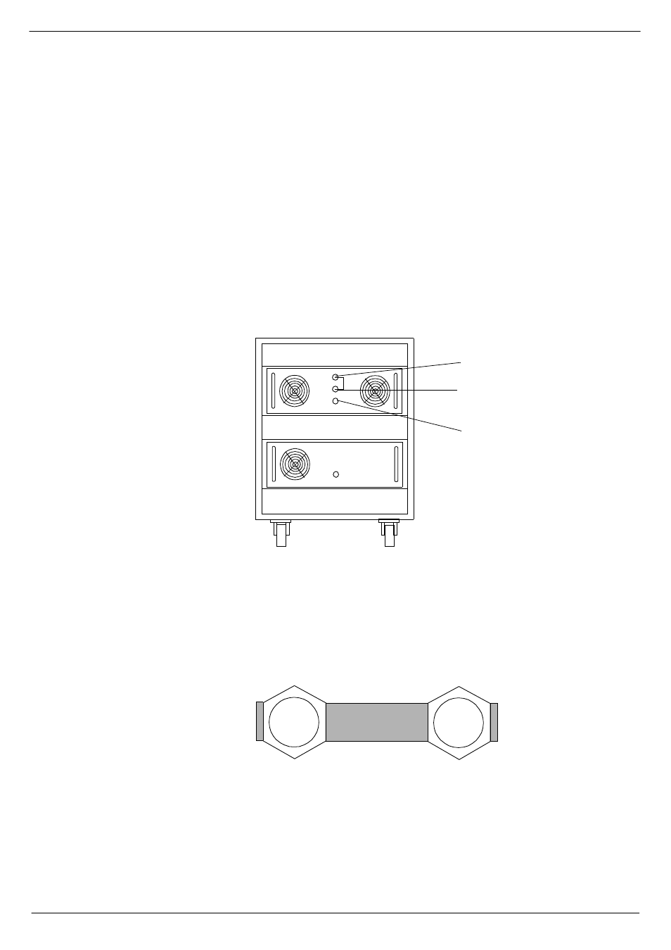
FIG 1-14. PSU system.
392$8',2#&20021
0$,16#($57+
0$,16#,1387
)5$0(
39
FIG 1-15. 0V, GROUND and FRAME terminals.