Cadac F-Type User Manual
Page 98
APP-II
F-Type
Revision F2005-2
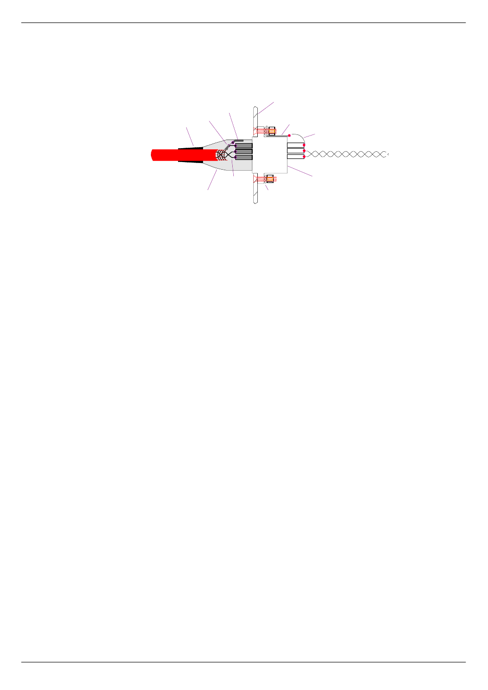
The chassis half of the connector is bonded to the metalwork with the usual nuts,
bolts and spiky washers. The solder tag should be as long as possible so that the
length of the 'short wire' is a minimum. The twisted pair (from the signal pins - pin 2 &
pin 3) are soldered onto the motherboard adjacent to the 'input RFI filter' compo-
nents.
%1##6ZLWFK00RGH#3RZHU#6XSSO\#8QLWV
CADAC 8019 and 8020 switch-mode power supply units were introduced during
November 1998. The a.c. input supply has been ‘standardised’ at 208V to 240V 50/
60Hz.
The 8019 “18V” unit is rated at 100A per rail and the 8020 “13V” unit is rated at 100A.
;34<#´4;9µ#VZLWFK0PRGH#SRZHU#VXSSO\#XQLW
The 8019 ±18v unit is based on two ADVANCE F20006 ‘power-blocks’, with addi-
tional circuitry as shown on CADAC drawing number C3.8015.
The a.c. input is connected to the PSU via a 3-core cable, CMA reference 3183TQ –
BASEC approved, rated at 20A.
Under no circumstances, should the 8019 PSU be used without a SAFETY EARTH
connection.
Failure to follow this instruction is both a fire and safety hazard.
5H0FDOLEUDWLQJ#DQ#´4;9µ#368
You will need CADAC drawings 8015 and 8023A.
TEST EQUIPMENT: Digital volt-meter, probe (must not be referenced to mains
earth), insulated adjustment tool.
WARNING! DO NOT remove cover unless you are qualified to service the parts
underneath it. UNDER NO CIRCUMSTANCES should anyone attempt to remove the
covers of the power blocks.
1.
Place the power supply on a flat surface and remove the top cover. Connect a
load to an O/P connector that is capable of drawing 40A per rail. The load must
draw the same current from each rail.
2.
Turn on the PSU and press the START button.
TW ISTED PAIR
W ITH BRAIDED
SCREEN
STRAIN RELIEF
PIGTAIL
SH ELL GROUN D TAG
XLR
M ETAL SHELL
W ITH CO NDUCTIVE FINISH
TW ISTED PAIR
M ETAL PANEL
SPIKY W ASH ER
LONG SOLDER TAG
SH ORT W IRE
TW ISTED PAIR TO FILTER ON PCB
XLR CHASSIS CONN ECTOR W ITH
CONDUCTIVE SURFACE AND
M ULTI-POINT BOND TO SH ELL
OF CABLE CONNECTOR
FIG APP -1. XLR connections.