Appendix b – cable lengths, Appendix c – click 221 user reference guide – Wavetronix SmartSensor Matrix (SS-225) - User Guide User Manual
Page 104
APPENDIX
103
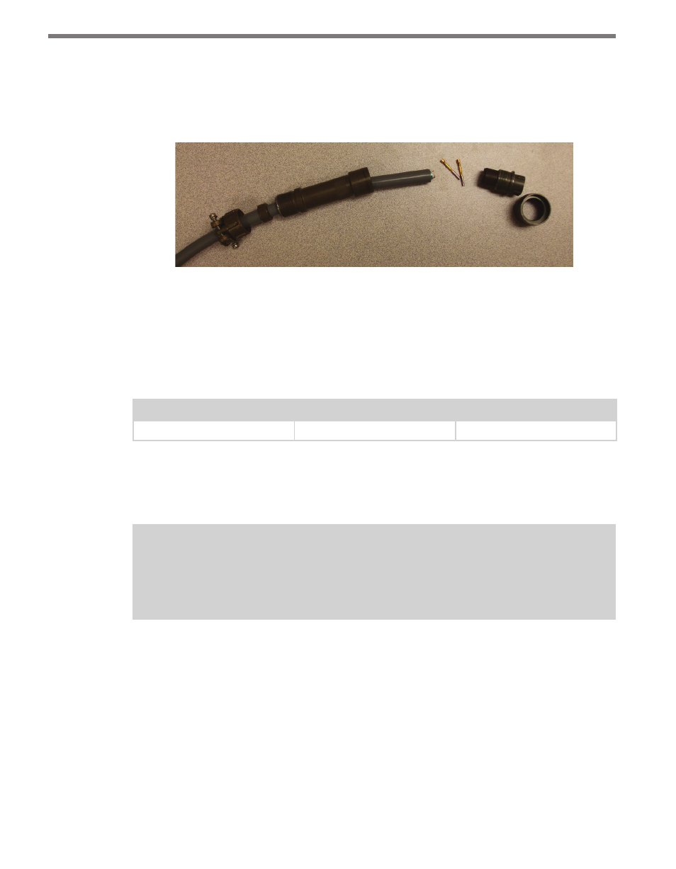
during the threading process, connect the plug and coupling ring to a sensor connec-
tor receptacle.
9 Press all of the connector parts together. Thread the strain relief onto the back shell.
10 Tighten the strain relief screws on the back.
Figure A.2 – Connector Sub-assembly Parts
Appendix B – Cable Lengths
It is recommended that the sensor be powered by 24 VDC to achieve reliable operation up
to 500 ft. (152.4 m) away. Table B.1 lists maximum cable lengths for 12 and 24 VDC.
Power Wire Gauge
24 Volts
12 Volts
20 AWG
500 ft. (152.4 m)
90 ft. (27.4 m)
Table B.1 – Maximum Cable Length for Power (ft)
For communications, both of the sensor’s RS-485 communication ports operate at 9600
bps.
Note
Contact Wavetronix Technical Services if you have a need for a cabled connection over
500 ft. (152.4 m).
Appendix C – Click 221 User Reference Guide
The Click 221 is a DC 8 A surge protector (8 A is the maximum rating of a T-bus connec-
tor). The DC source voltage and PE (protective earth) should be wired into the screw ter-
minals on the bottom side of the device. A 12 AWG protective earth wire is recommended.
The device works with up to 8 A of continuous current at a maximum of 28 VDC.