Click 114 input mapping dip switch settings, Click 112 dip switch settings – Wavetronix SmartSensor Matrix (SS-225) - User Guide User Manual
Page 32
CHAPTER 3 • CONTACT CLOSURE COMMUNICATION
31
Note
An advantage of using the DIP switches for configuration is that if you ever need to
replace a Click 112/114, you can simply set the DIP switches on the new card to match
the pattern of the DIP switches on the card you are replacing, then slide the new one
into the same slot in the detector rack.
Click 114 Input Mapping DIP Switch Settings
On a Click 114, channel group 1 comprises input channels 1–4. When this channel group
is selected; sensor channel 1 will be mapped to output channel 1; sensor channel 2 will be
mapped to output channel 2; sensor channel 3 will be mapped to output channel 3; and sen-
sor channel 4 will be mapped to output channel 4.
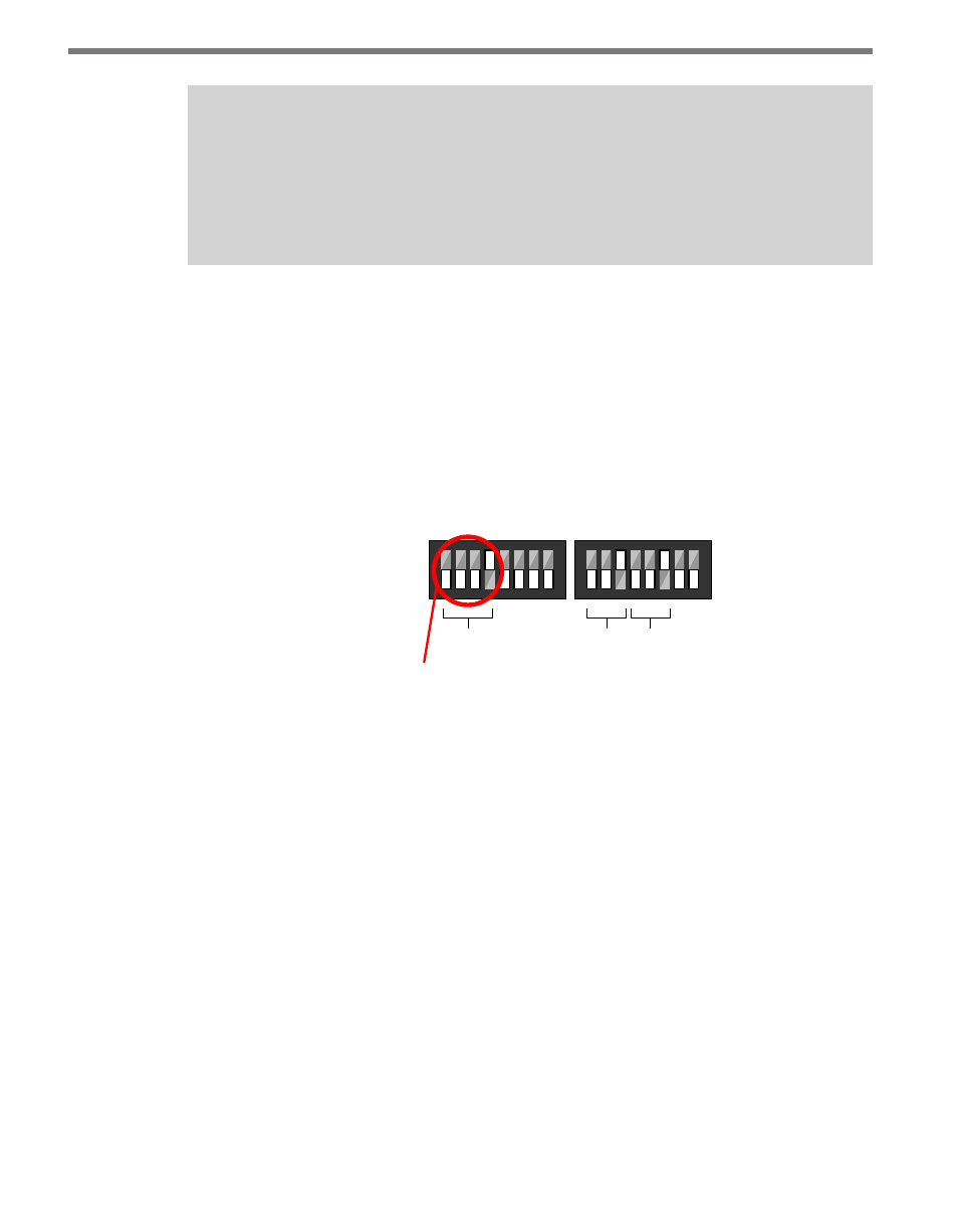
Use Figure 3.3 below to set the DIP switch settings to select channel group 1:
1 2 3
4
5 6 7 8
1 2
3
4 5
6
7 8
On
Off
Click 114 – Selects Matrix channels 1 through 4 for output
Channel
Group
Bus 1
Bus 2
S4
S5
Input Mapping Switches Baud Rate Switches
Figure 3.3 – Click 114 DIP Switch Settings
Click 112 DIP Switch Settings
On a Click 112, channel group 1 comprises input channels 1 and 2, where sensor channel 1
will be mapped to output channel 1 and sensor channel 2 will be mapped to output chan-
nel 2. In order to map sensor channel 3 to output channel 1 and sensor channel 4 to output
channel 2, you will need to select channel group 2.
If you are using two Click 112 devices, you will need to set the DIP switches differently for
each card and daisy-chain the cards together using bus 1.
Figure 3.4 below shows how to set the DIP switches on the Click 112 card on the left. This
will select Matrix output channels 1 and 2 for output.