Wavetronix SmartSensor Matrix (SS-225) - User Guide User Manual
Page 27
26
CHAPTER 2 • CABINET SOLUTIONS
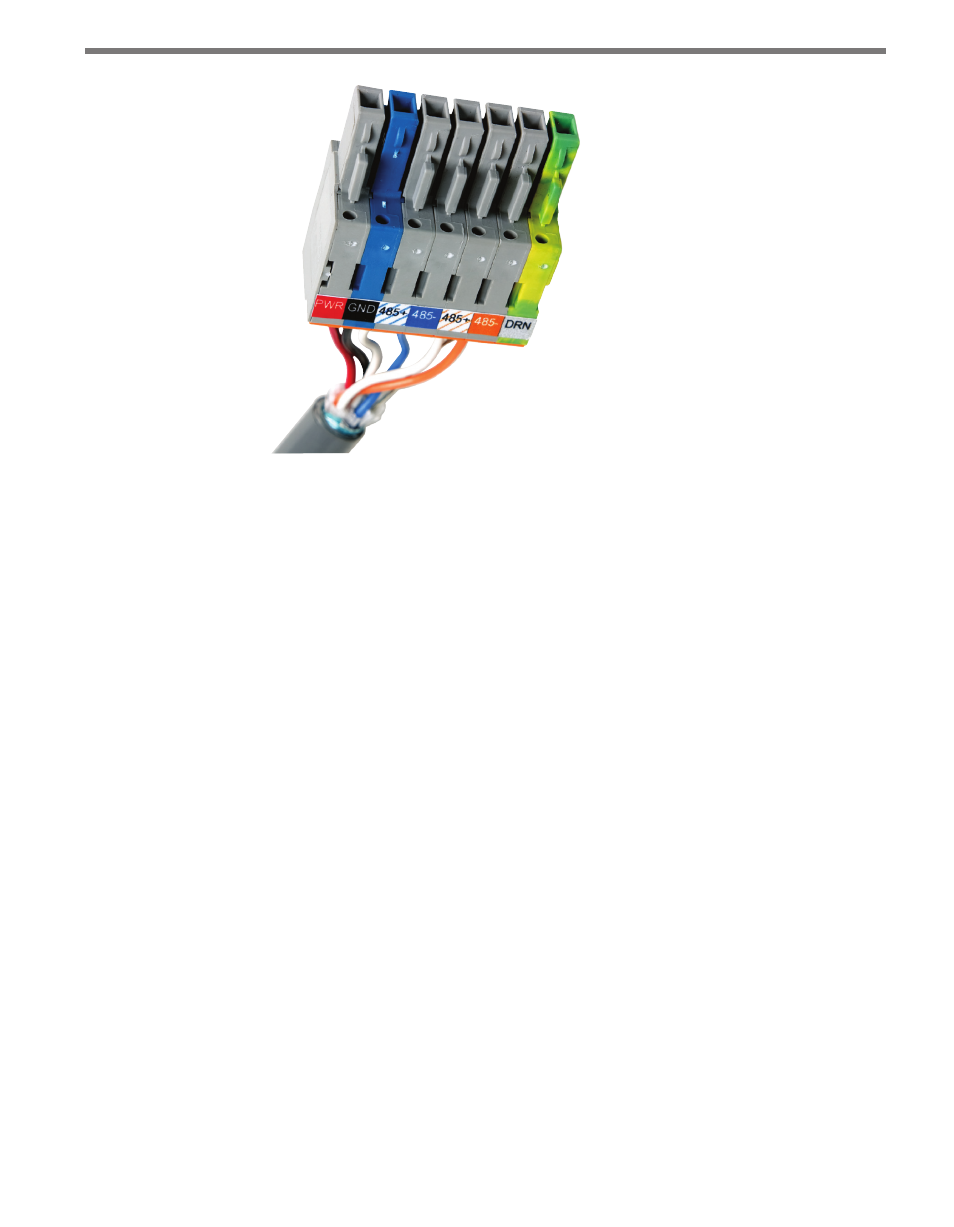
Figure 2.7 – Color Label on Plug-in Terminals
Each 6-conductor cable has one DC power wire pair, two RS-485 communication pairs,
and a drain wire (see the above figure). Follow the steps below to land the sensor cables into
the plugs.
1 After routing your SmartSensor 6-conductor cable into the cabinet, carefully strip back
the cable jacket and shielding on the service end of the cable.
2 Open the insulation displacement connectors on the plug by inserting a small screw-
driver into each square slot and rocking it back.
3 Insert the wire leads into the bottom side of the plug-in terminal according to the color
code shown in Table 2.1 and Figure 2.7. Make sure the wires are completely inserted
in the terminal.
4 Close the insulation displacement connector by reinserting the screwdriver into the
square slot and rocking it forward. The plug-in terminals will automatically complete
the electrical connection. There is no need to manually strip the insulation on the end
of each wire.
Do not strip the service end of the cable until after it has been routed through conduit. The
cable should be one continuous run without any splices.