2 installation method, Installation method and direction, Space between servopack units – Yaskawa Junma Series SERVOPACK User Manual
Page 18: 2 ins, Inst, English, 2 installation method e-17, Servopack installation plate m4 screw
2.2 Installation Method
E-17
English
2.2 Installation Method
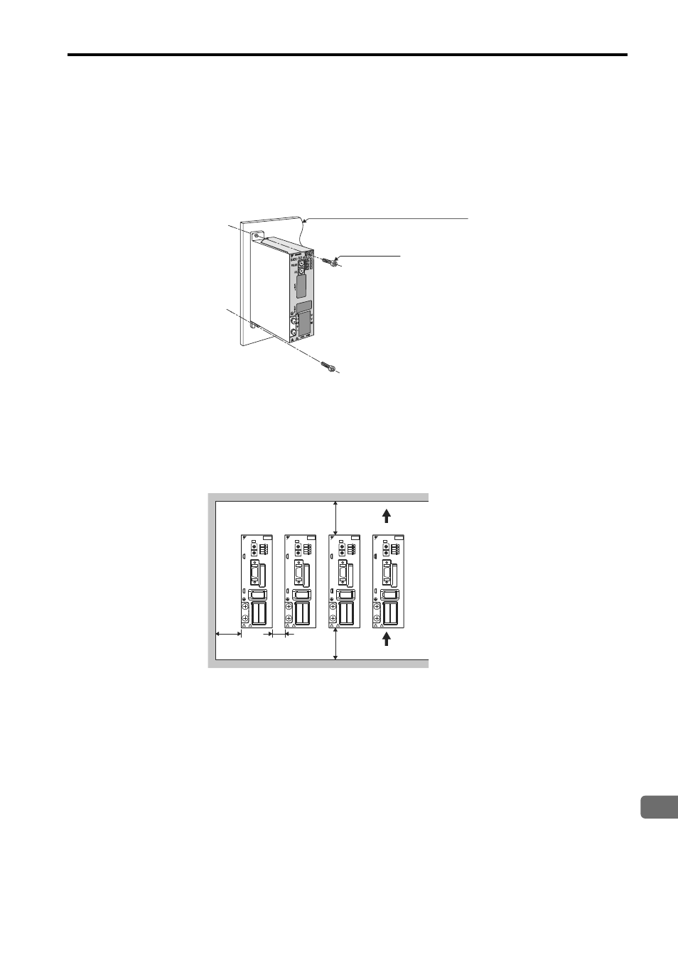
Installation Method and Direction
• Install the SERVOPACK perpendicular to the wall. The SERVOPACK contains a built-in fan for cooling and
must be mounted in the specified direction.
• Connect the mounting holes securely to the mounting surface with M4 screws (two mounting holes).
Space between SERVOPACK Units
• Be sure to keep a space between adjacent SERVOPACK units if they are mounted inside the control panel so that
the units can be cooled.
• Do not cover the inlet or outlet parts and prevent any foreign objects, such as metallic fragment, or combustibles
from entering the product.
Failure to observe this caution may cause internal elements to deteriorate resulting in malfunction or fire.
SERVOPACK installation plate
M4 screw
200V
YASKAWA
SJDE- 04 APA-OY
CTL
AL1
AL2
AL3
PWR
L1
L2
+
CNA CNB
U
V
W
-
200V
YASKAWA
SJDE- 04 APA-OY
FIL
PULSE
FIL
PULSE
FIL
PULSE
FIL
PULSE
CTL
AL1
AL2
AL3
PWR
L1
L2
+
CNA CNB
U
V
W
-
200V
YASKAWA
SJDE- 04 APA-OY
CTL
AL1
AL2
AL3
PWR
L1
L2
+
CNA CNB
U
V
W
-
200V
YASKAWA
SJDE- 04 APA-OY
CTL
AL1
AL2
AL3
PWR
L1
L2
+
CNA CNB
U
V
W
-
50 mm
min.
50 mm
min.
30 mm
min.
10 mm
min.
Air outlet direction
Air inlet direction
C
N
2
C
N
1
C
0
8
9
A
B DE
F
45
3
2
6
7
1
C
0
8
9
A
B DE
F
45
3
2
6
7
1
C
N
2
C
N
1
C
0
8
9
A
B DE
F
45
3
2
6
7
1
C
0
8
9
A
B DE
F
45
3
2
6
7
1
C
N
2
C
N
1
C
0
8
9
A
B DE
F
45
3
2
6
7
1
C
0
8
9
A
B DE
F
45
3
2
6
7
1
C
N
2
C
N
1
C
0
8
9
A
B DE
F
45
3
2
6
7
1
C
0
8
9
A
B DE
F
45
3
2
6
7
1