Yaskawa Junma Series SERVOPACK User Manual
Page 35
3.9 Wiring the Servomotor Main Circuit Cable Connector (CNB)
E-34
4. If using the servomotor to drive a vertical axis, provide a circuit to turn the holding brake
ON so that the movable section will not be pulled down by gravity when the power sup-
ply of the SERVOPACK is turned OFF.
Failures caused by incorrect wiring or wrong voltage application in the brake circuit may damage
the equipment or cause an accident resulting in death or injury.
Follow the procedures and instructions for wiring and trial operation precisely as described in this
manual.
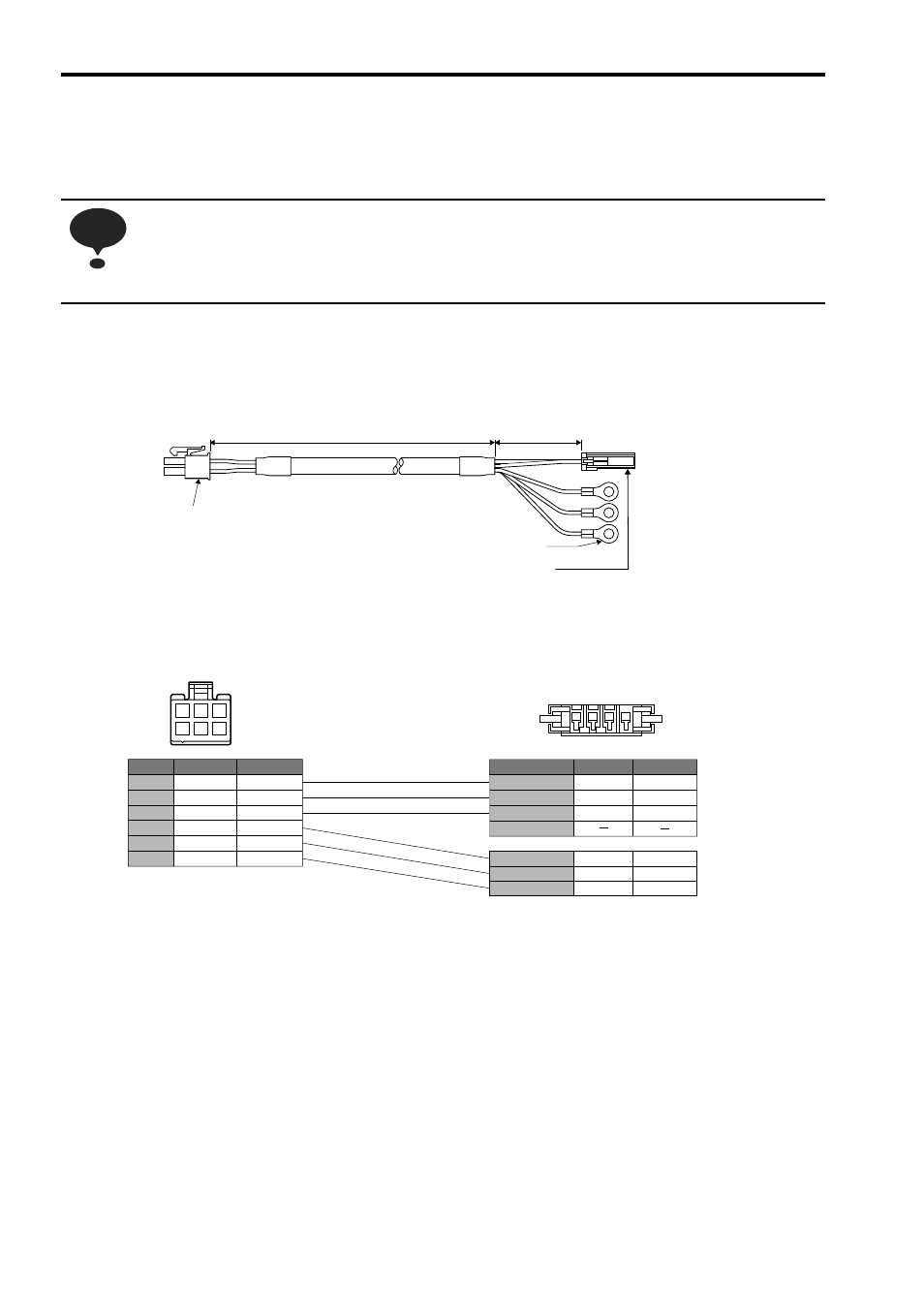
Connection Diagram for Standard Servomotor Main Circuit Cable
If a user-prepared servomotor main circuit cable is used, refer to the following connection diagram for the standard
cable (JZSP-CHM030- Cable with Connectors on Both Ends) and wire the servomotor main circuit cable.
NOTE
Connector (crimp type)
Receptacle: 5557-06R-210
Terminal: 5556T (Chain) or
5556TL (Loose wires)
(Molex)
SERVOPACK end
L
50mm
Motor end
Connector (crimp type)
Receptacle: F32FSS-04V-KY
Rececontact: SF3F-01GF-P2.0 or SF3F-41GF-P2.0
(JST. Mfg. Co., Ltd.)
M4 crimped terminal
1
4
SERVOPACK Connector
(Viewed from soldered side)
1 2 3
4 5 6
Servomotor Connector
(Viewed from cable insertion side)
Lead Color
Signal Name
Pin No.
Red
White
Blue
Green/Yellow
Black
Black
Phase U
Phase V
Phase W
FG
∗1
Brake
∗2
Brake
∗2
Lead Color
Signal Name
Red
White
Blue
Green/Yellow
Black
Black
Phase U
Phase V
Phase W
FG
Brake
Brake
Pin No.
1
2
3
4
5
6
1
2
3
4
Crimped terminal
Crimped terminal
Crimped terminal
∗1: Connect the FG pin to the grounding terminal of the SERVOPACK.
∗2: No polarity for connection to the brake.