English – Yaskawa Junma Series SERVOPACK User Manual
Page 82
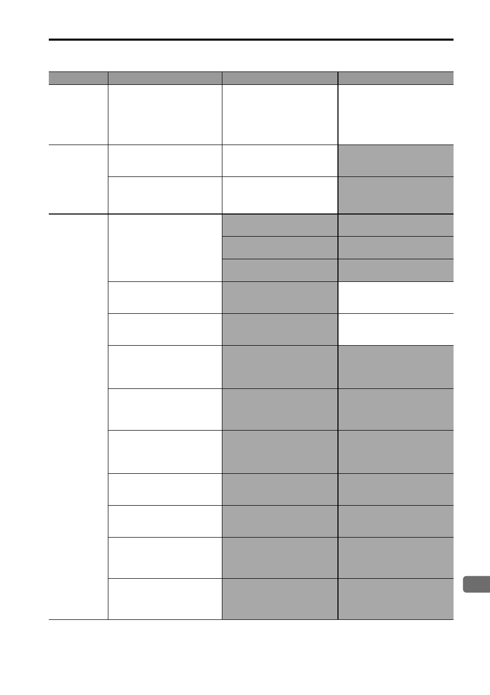
6.2 Troubleshooting for Malfunctions when Alarm Indicators Are Not Lit
E-81
English
The holding
brake does
not work.
The holding brake power is
turned ON.
Check to see if the holding
brake power is turned ON.
Design the circuit so that the
holding brake is turned OFF
when the holding brake
needs to hold the load when
the servomotor comes to a
stop.
Servomotor
does not stop
operation
smoothly or
at all when
servo is
turned OFF.
The servomotor is over-
loaded.
Check to see if the load is
excessive or the servomotor
speed is too high.
Reconsider the load
conditions and replace the
SERVOPACK.
A stop circuit fault occurred.
−
Replace the SERVOPACK.
Abnormal
noise from
Servomotor
or machine
vibrates, or
an overshoot
occurs.
Mounting not secured.
Check to see if there are any
loose mounting screws.
Tighten the mounting screws.
Check to see if the coupling
is misaligned.
Align the coupling.
Check to see if the coupling
is unbalanced.
Balance the coupling.
Defective bearings
Check for the noise and
vibration around the bear-
ings.
If there is a fault, contact your
Yaskawa representative.
Vibration source on the
driven machine
Foreign matter, looseness, or
deformation on the machine
movable section.
(Contact the machine manu-
facturer.)
Noise interference due to
incorrect input signal cable
specifications.
Be sure that the twisted-pair
or shielded twisted-pair cable
with a core of at least
0.08 mm
2
is used.
Use the specified input signal
cables.
Noise interference because
the input signal cable is
longer than the applicable
range.
The wiring distance must be
3 m max.
Shorten the wiring distance
for input signal cable to 3 m
or less.
Noise interference because
the encoder cable specifica-
tions are incorrect.
Check to see if a shielded
twisted-pair cable with a core
of at least 0.12 mm
2
is being
used.
Use a cable that meets the
encoder cable specifications.
Noise interference because
the encoder cable is longer
than the applicable range.
Check the length of the
encoder cable.
The wiring distance must be
20 m or less.
Noise is entering the
encoder cable because the
sheath is damage.
Check to see if the encoder
cable is damaged.
Modify the encoder cable lay-
out so the cable is not sub-
jected to surge.
Excessive noise interfer-
ence on encoder cable.
Check to see if the encoder
cable is bundled with high-
current lines or near high-
current lines.
Install a surge absorber (for
lightning surge) on the
encoder cable.
FG potential varies due to
the influence of machines
such as a welder at the ser-
vomotor.
Check to see if the machine
is correctly grounded
properly.
Ground the machine
separately from the PG’s FG.
Problem
Cause
Inspection Items
Corrective Action