Electronic gear ratio setting examples, English, 4 electronic gear e-49 – Yaskawa Junma Series SERVOPACK User Manual
Page 50
5.4 Electronic Gear
E-49
English
Electronic Gear Ratio Setting Examples
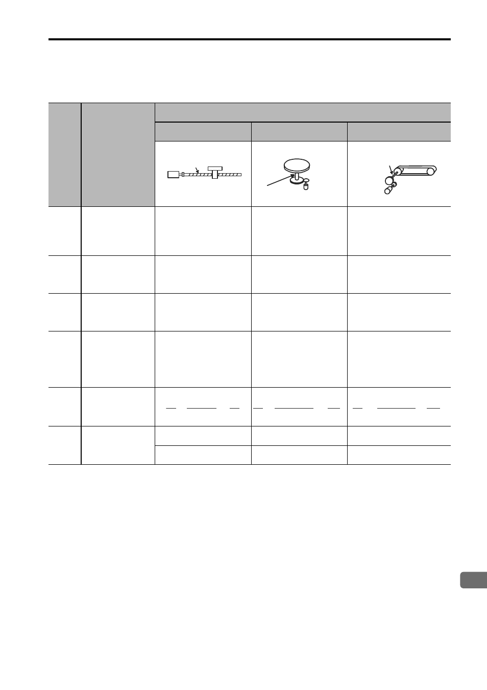
The following examples show electronic gear ratio settings for different load configurations.
Step
Operation
Load Configuration
Ball Screw
Disc Table
Belt and Pulley
1
Check machine
specifications.
• Ball screw pitch:
6 mm
• Gear ratio: 1/1
Rotation angle per
revolution: 360
°
Gear ratio: 1/10
Pulley diameter: 100 mm
(pulley circumference:
314 mm)
• Gear ratio: 1/50
2
Check the
encoder resolu-
tion.
65536 (16-bit)
65536 (16-bit)
65536 (16-bit)
3
Determine the
reference unit
used.
Reference unit: 0.001
mm (1
μm)
Reference unit: 0.01
°
Reference unit: 0.005
mm (5
μm)
4
Calculate the
travel distance
per load shaft
revolution.
(Reference unit)
6 mm/0.001 mm=6000
360
°/0.01°=36000
314 mm/0.005 mm
=62800
5
Calculate the
electronic gear
ratio.
6
Set parameters.
Pn20E: 65536
Pn20E: 655360
Pn20E: 3276800
Pn210: 6000
Pn210: 36000
Pn210: 62800
Ball screw
pitch: 6 mm
16-bit encoder
Load shaft
Reference unit: 0.001 mm
16-bit encoder
Load shaft
Reference unit: 0.01
°
Gear ratio:
1/10
Load shaft
Gear ratio
1/50
Reference unit: 0.005 mm
Pulley diameter:
100 mm
16-bit encoder
65536
6000
1
1
=
B
A
×
B
A
65536
36000
10
1
=
×
B
A
65536
62800
50
1
=
×