2 connecting protective earth, Connecting protective earth – KACO Powador XP200-HV TL User Manual
Page 19
Advertising
Installation
Operating Instructions Powador XP200-HV TL, XP250-HV TL, XP350-HV TL_EN
Page 19
Electrician
1
2
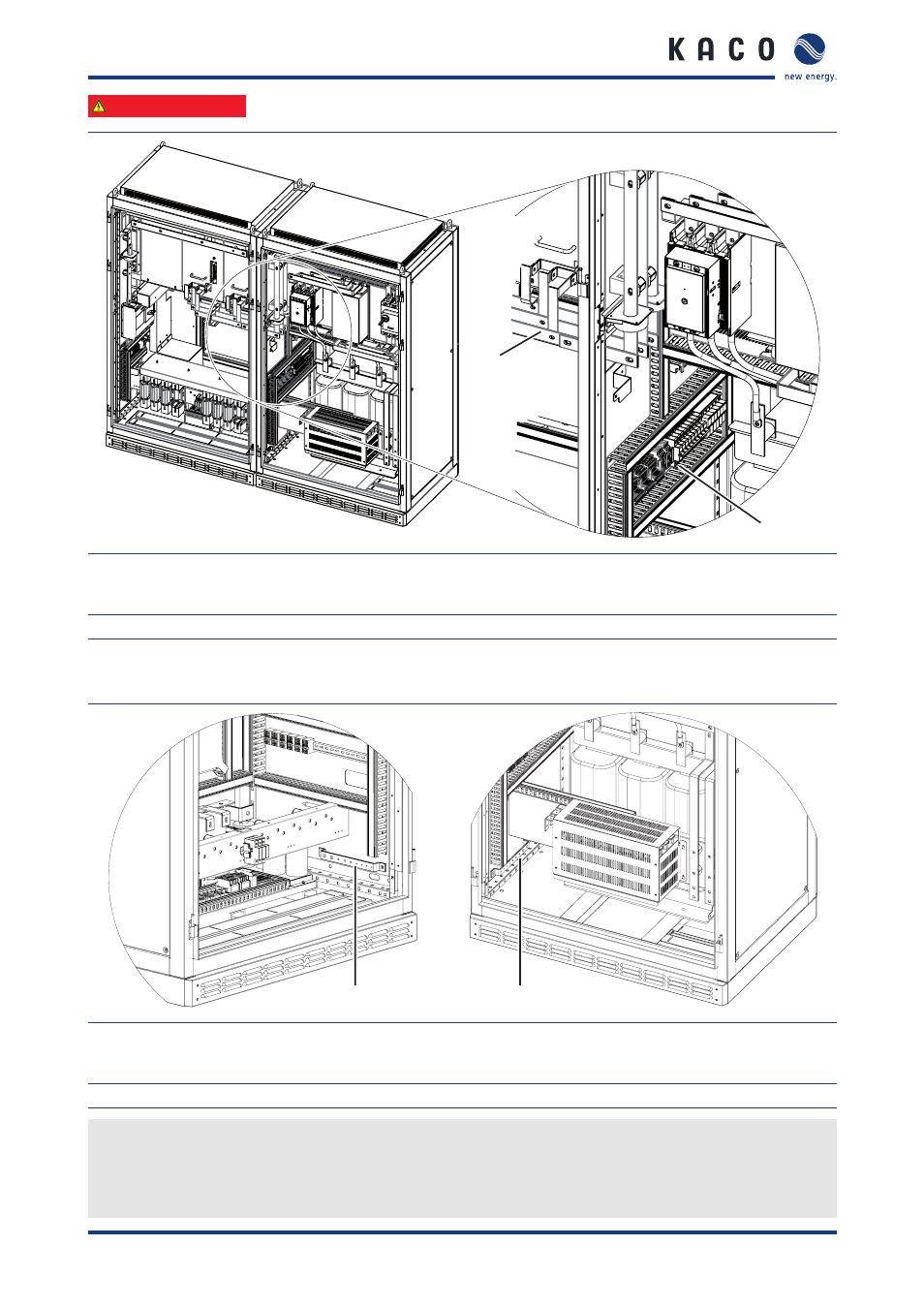
Figure 9: Electrical connection for the cabinets
Key
1
Busbar connection
2
Controller connection on the right side
7.2
Connecting protective earth
1
2
Figure 10: Protective earth connections
Key
1
PE busbar in the left inverter cabinet
2
PE busbar in the right inverter cabinet
Connecting the PE busbars
The PE (protective earth) busbars are located on the right side of the left inverter cabinet (Figure 10, item 1) and on
the left side of the right inverter cabinet (Figure 10, item 2).
"
Connect the wires for both PE busbars.
Advertising
This manual is related to the following products: