7 preparing the start-up, Preparing the start-up, 5 connecting the remote power control – KACO Powador XP200-HV TL User Manual
Page 34
Installation
Page 34
Operating Instructions Powador XP200-HV TL, XP250-HV TL, XP350-HV TL_EN
Electrician
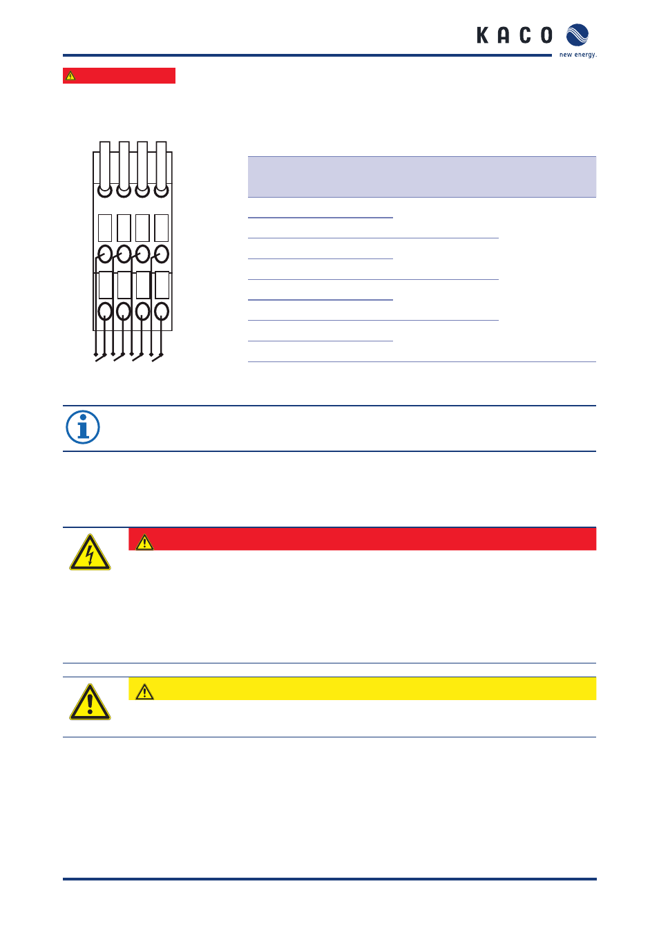
7.6.5 Connecting the remote power control
Remote power control (RPC) to connect grid feed-in management
-RPC
1b 2b 3b 4b
1a 2a 3a 4a
Terminal
number
Terminal
designation
Specification
Wire cross-
section, max.
1a
RPC1 N
100% generation of
electrical power
AWG 20
(0.75 mm
2
)
1b
RPC1 P
2a
RPC2 N
60% generation of
electrical power
2b
RPC2 P
3a
RPC3 N
30% generation of
electrical power
3b
RPC3 P
4a
RPC4 N
0% generation of
electrical power
4b
RPC4 P
Figure 35: RPC connection and wiring
Table 15: Connections for remote power control (RPC)
NOTE
›
After the successful electrical installation of the inverters and the connection of all interfaces
mount the plexiglas covers to ensure safe operation.
7.7
Preparing the start-up
After the electrical connection and the connection of the interfaces, the inverter, especially the settings for the
interfaces, must be configured. The inverter has to be started-up for configuration.
DANGER
Lethal voltages are still present in the terminals and lines of the inverter even after the inver-
ter has been switched off and disconnected!
Coming into contact with the lines and terminals in the inverter will cause serious injury or death.
Only authorised electricians who are approved by the supply grid operator may open, install and
maintain the inverter.
›
Keep all doors and covers closed when the unit is in operation.
›
Do not touch the lines and terminals when switching the unit on and off.
CAUTION
Internal short circuit by incorrect connection
›
Do not use the external and the internal power supply at the same time.