3 connecting the transformer – KACO Powador XP200-HV TL User Manual
Page 21
Installation
Operating Instructions Powador XP200-HV TL, XP250-HV TL, XP350-HV TL_EN
Page 21
Electrician
DANGER
Lethal voltages may be present in an IT grid!
Under operating conditions voltages up to 1200 V can be present between phase and ground.
›
Ensure proper dimensioning of the cable between inverter and transformer in terms of voltage
resistance (minimum dimensioning voltage: 1200 V)
›
Make sure that no ground faults or short-circuits can occur. Otherwise the inverter may be dama-
ged.
7.3.3 Connecting the transformer
Connection data
Max. cable cross-section
300 mm²
Connection bolt
M10
Tightening torque for AC terminal connections
40 ... 50 Nm
NOTE
If the cables are connected to the
wrong terminals, the inverter does not
operate.
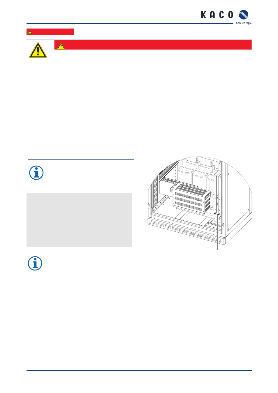
1
Figure 11: Bottom of the right cabinet
1
AC connections
Connecting the cables
Each cable corresponds to one phase.
"
Guide the cables through the opening.
Be sure to connect each of the cables to the cor-
rect terminal.
"
Screw down the cables.
"
Check to make sure that all of the cables are
securely attached.
NOTE
If larger diameters are necessary, it is
also possible to use two cables for one
phase (e.g. 2 x 240 mm²)