4 connecting the analogue input – KACO Powador XP200-HV TL User Manual
Page 32
Advertising
Installation
Page 32
Operating Instructions Powador XP200-HV TL, XP250-HV TL, XP350-HV TL_EN
Electrician
-RS485
A(DATA–)
B(DATA+)
1b 2b 3b 4b
1a 2a 3a 4a
GND
Jumper
Signal transceiver
Figure 28: RS485-2 termination disposal
NOTE
Terminating resistors need to be installed at both ends of the device within the communication
railroad.
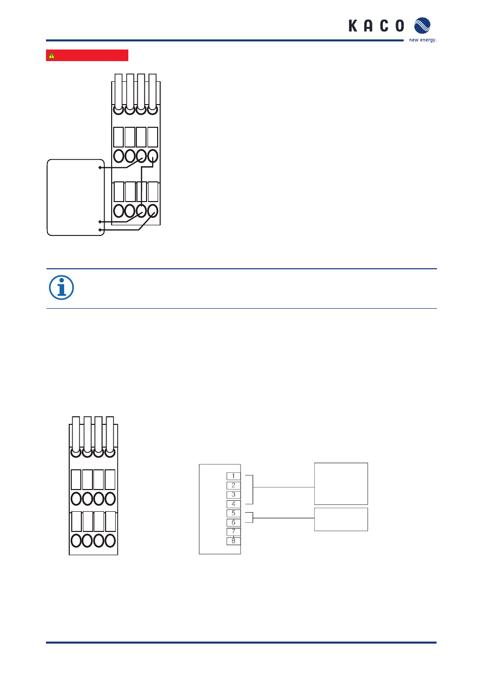
7.6.4 Connecting the analogue input
The inverter has four analogue connections.
1a, 1b, 2a, 2b
Solar sensor
3a, 3b
PT 1000 ambient temperature sensor
4a, 4b
Reserve
Input range
0 ... 10 V
-UAI
1b 2b 3b 4b
1a 2a 3a 4a
A
nal
ogu
e
in
put
Solar
sensor
PT1000
Figure 29: Analogue user input
Figure 30: Connection diagram of the analogue interface
Advertising
This manual is related to the following products: