Rs485 – KACO Powador XP200-HV TL User Manual
Page 31
Installation
Operating Instructions Powador XP200-HV TL, XP250-HV TL, XP350-HV TL_EN
Page 31
Electrician
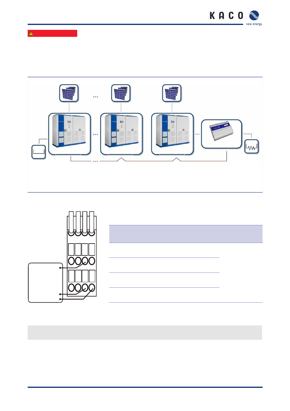
7.6.3 Connecting the RS485-2 interface
The RS485-2 interface is the interface for the MMI’s internal data logger, or for the external Powador-proLOG data
logger.
Powador-proLOG settings
Termination
disposal
(Jumper)
XP250-HV #2
Installation
termination
resistor (120 Ω)
RS485
XP250-HV #3
XP250-HV #N
Powador-proLOG #1
Figure 26: Powador-proLOG in RS485 network (XP250-HV)
Terminal connections
-RS485
A(DATA–)
B(DATA+)
1b 2b 3b 4b
1a 2a 3a 4a
GND
Signal transceiver
Terminal
number
Terminal
designation
Specification
Wire cross-
section, max.
3a
RS485 A2
RS485 signal A2
(DATA +)
AWG 20
(0.75 mm
2
)
3b
RS485 B2
RS485 signal B2
(DATA –)
4a
RS485 G2
RS485 data
transmission GND 2
4b
RS485 C2
Terminal for
terminating resistor
Figure 27: RS485-2 connection
Table 12: Connections for RS485-2
"
A terminating resistor (120 Ω, 0.5 W, 1 %) is installed on the main control board (XCU).
For termination disposal use a jumper between RS485 A2 (3a) and RS485 C2 (4b).