Antennas, E 92 – ProSoft Technology RLXIB-IHA-A User Manual
Page 92
Reference
RLXIB-IHA ♦ 802.11a
User Manual
RadioLinx® 802.11a Industrial Hotspot
Page 92 of 123
ProSoft Technology, Inc.
July 25, 2013
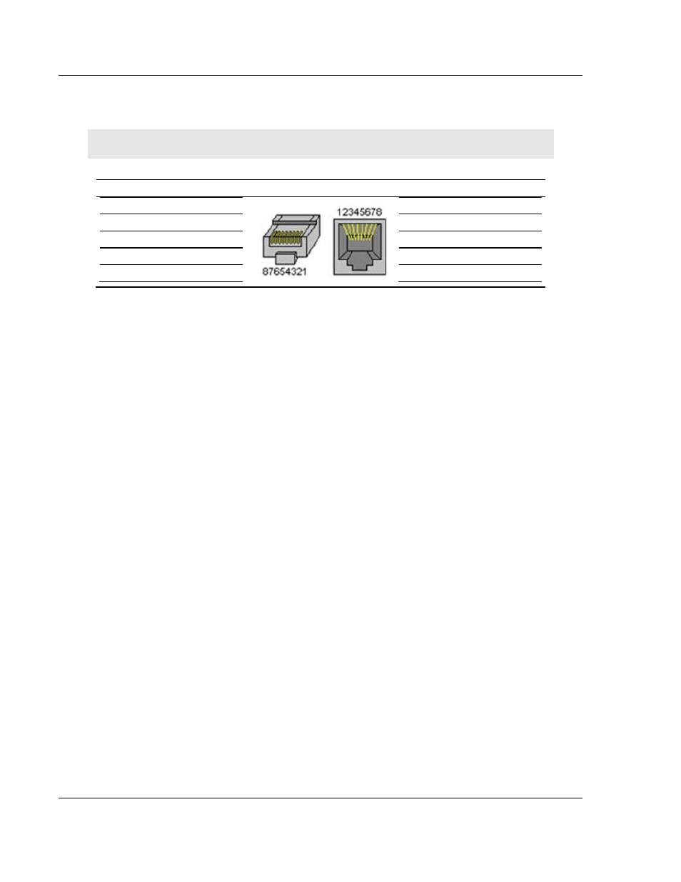
6.2.3 Ethernet Cable Configuration
Note: The standard connector view shown is color-coded for a straight-through cable.
Crossover cable
Straight- through cable
RJ-45 PIN
RJ-45 PIN
1 Rx+
3 Tx+
2 Rx-
6 Tx-
3 Tx+
1 Rx+
6 Tx-
2 Rx-
RJ-45 PIN
RJ-45 PIN
1 Rx+
1 Tx+
2 Rx-
2 Tx-
3 Tx+
3 Rx+
6 Tx-
6 Rx-
6.3
Antennas
When you are ready to connect antennas to the radio, see Connecting antennas
(page 28).
You must also consider three important electrical characteristics when selecting
antennas:
Antenna pattern (page 92)
Antenna gain (page 93)
Antenna polarity (page 93)
Antenna location, spacing, and mounting (page 96)
6.3.1 Antenna Pattern
Information between two wireless devices is transferred via electromagnetic
energy radiated by one antenna and received by another. The radiated power of
most antennas is not uniform in all directions and has varying intensities. The
radiated power in various directions is called the pattern of the antenna. Each
antenna should be mounted so that its direction of strongest radiation intensity
points toward the other antenna or antennas with which it will exchange signals.
Complete antenna patterns are three-dimensional, although often only a two-
dimensional slice of the pattern is shown when all the antennas of interest are
located in roughly the same horizontal plane, along the ground rather than above
or below one another.
A slice taken in a horizontal plane through the center (or looking down on the
pattern) is called the azimuth pattern. A view from the side reveals a vertical
plane slice called the elevation pattern.