Dsv-j2 general purpose output connection diagram, Typical application dsv-j2 gpio cable – Doremi DSV-J2 User Manual
Page 52
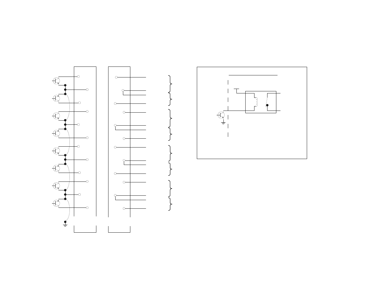
13 Appendix A: General Purpose Output Connection Diagram
Typical Application
DSV-J2
GPIO Cable
GPO 0
+5V up to +24V
DSV-J2
Each general purpose output has an open collector stage. The stage can
turn on relays with voltage range of +5V to +24V, and current up to 200 mA.
DSV-J2 General Purpose
Output Connection Diagram
GPIO Male Connector
GPIO Cable Female Connector
GPO 7
GPO 6
GPO 5
GPO 4
GPO 3
GPO 2
GPO 1
GPO 0
Pin 1
Pin 14
Pin 2
Pin 15
Pin 3
Pin 16
Pin 4
Pin 17
Pin 5
Pin 18
Pin 6
Pin 19
...
Common
Ground
In the schema on the left, Pin x means Pin number x on the GPIO
connector (DB25 connector)
GND
GPO 7
GPO 6
GND
GPO 5
GND
GPO 4
GND
GPO 3
GND
GPO 2
GND
GPO 1
GND
GPO 0
GND
GPO 7
GPO 6
GPO 5
GPO 4
GPO 3
GPO 2
GPO 1
GPO 0
...
Pin 1
Pin 14
Pin 2
Pin 15
Pin 3
Pin 16
Pin 4
Pin 17
Pin 5
Pin 18
Pin 6
Pin 19
DSV.OM.000391.DRM
Page 52 of 68
Version 1.2
Doremi Labs