Dsv-j2 general purpose input connection diagram, Dsv-j2 gpio cable, Typical application 1 – Doremi DSV-J2 User Manual
Page 53: Typical application 2, Dsv-j2
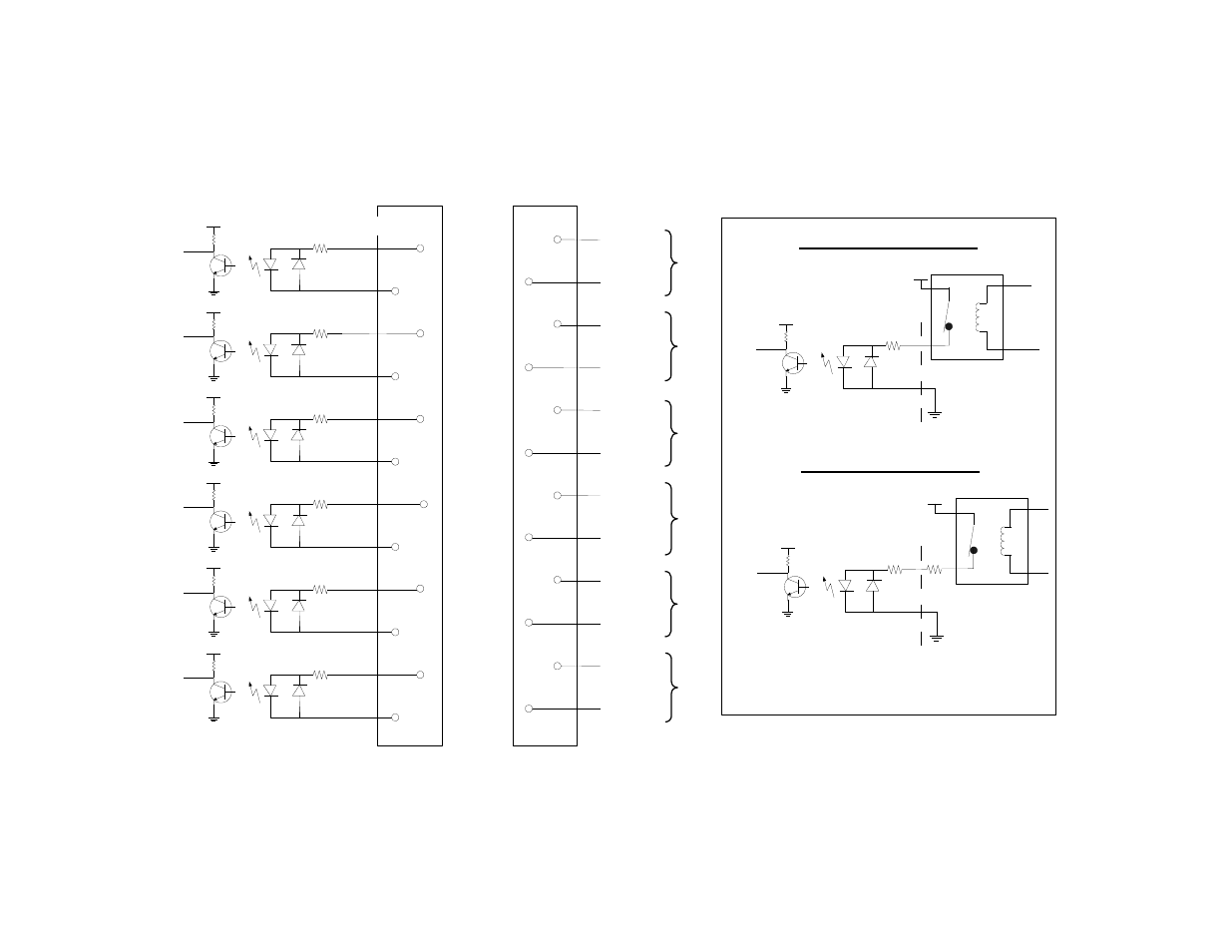
14Appendix B: General Purpose Input Connection Diagram
DSV-J2
GPIO Cable
GPIO Male Connector
GPIO Cable Female Connector
...
Typical Application 1:
DSV-J2
DSV-J2 General Purpose
Input Connection Diagram
GPI 0
+5V
270 Ohm
+5V up to +12V
Typical Application 2:
DSV-J2
Each general purpose input will turn on if you feed a current between
4mA and 30mA.
GPI 0
+5V
270 Ohm
+12V up to +24V
330 Ohm
(+)
(-)
(+)
(-)
GPI 5
GPI 4
GPI 3
GPI 2
GPI 1
GPI 0
plus
plus
plus
plus
plus
plus
Pin 8
Pin 20
Pin 9
Pin 21
Pin 10
Pin 22
Pin 12
Pin 23
Pin 11
Pin 24
Pin 25
Pin 13
...
+5V
+5V
+5V
+5V
+5V
+5V
270 Ohm
270 Ohm
270 Ohm
270 Ohm
270 Ohm
270 Ohm
minus
minus
minus
minus
minus
minus
GPI 5 (-)
GPI 5 (+)
GPI 4 (+)
GPI 4 (-)
GPI 3 (+)
GPI 3 (-)
GPI 2 (+)
GPI 2 (-)
GPI 1 (+)
GPI 1 (-)
GPI 0 (+)
GPO 0 (-)
GPI 5
GPI 4
GPI 3
GPI 2
GPI 1
GPI 0
Pin 8
Pin 20
Pin 9
Pin 21
Pin 10
Pin 22
Pin 12
Pin 23
Pin 11
Pin 25
Pin 13
Pin 24
DSV.OM.000391.DRM
Page 53 of 68
Version 1.2
Doremi Labs