Using multiple interfaces, 1 using multiple interfaces – Bronkhorst EL-FLOW Prestige User Manual
Page 15
Bronkhorst High-Tech B.V.
EL-FLOW Prestige
15
9.17.084
Via the 9-pin sub-D side connector the instrument can be operated by means of:
Analog interface (section 3.3): 0…5 Vdc; 0…10 Vdc; 0…20 mA or 4…20 mA
Digital RS232 interface (section 3.4 and document 9.17.027): (FLOW-BUS (Propar) protocol)
Digital RS485 interface (section 3.5): (Modbus RTU, Modbus ASCII or FLOW-BUS protocols)
The following optional field bus interfaces can be installed:
FLOW-BUS interface (section 3.5 and document 9.17.024)
Modbus (RTU or ASCII) interface (section 3.5 and document 9.17.035)
PROFIBUS DP interface (section 3.6 and document 9.17.025)
DeviceNet
TM
interface (section 3.6 and document 9.17.026)
EtherCAT® interface (section 3.6 and document 9.17.063)
PROFINET interface (section 3.6 and document 9.17.095)
The interpretation of the LED indications and use of the micro switch button on top of the instrument is discussed in section 3.7
and section 3.8 respectively.
3.2.1
Using multiple interfaces
The analog interface is always present on EL-FLOW Prestige instruments. An interface to any available field bus is optional.
Operation via analog interface, RS232/RS485 (side connector) and an optional field bus (top connector) can be performed at the
same time. When using multiple interfaces, reading of parameters can be done simultaneously. When changing a parameter value,
the last value sent by any of the interfaces will be valid.
Control mode
A controller setpoint is accepted from either the analog or digital interface, but not both. Analog or digital operation is selected at
ordering and indicated on the instrument backside label. The inactive setpoint source is indicated between brackets (…), see
example below. The parameter ‘Control Mode’ indicates from which source a controller setpoint is accepted: analog or digital. See
section 4.2.2 for more information regarding the ‘Control Mode’ parameter.
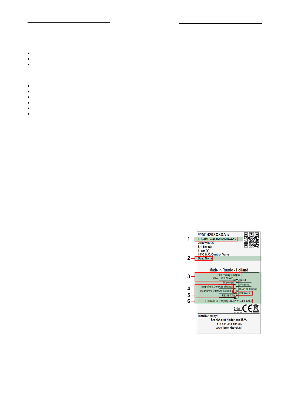
Factory communication settings
The factory selected communication and side connector pinning settings are indicated on the instrument backside label. See
example below for a description of the communication information indicated on the instrument label:
1. Model key (see explanation of the model key in section 1.5)
2. Field bus (top connector) (example: none)
3. Customized IO settings (pin 5), see section 4.4.1 for more
information (example: default setting)
4. Analog interface (pin 2, 3) (example: inactive setpoint
source, measure always available)
5. Digital interface (pin 1, 6) (example: RS232, active setpoint
source)
6. Side connector digital interface settings (protocol, medium,
baud rate, parity) (example: FLOW-BUS (Propar)
communication over RS232 interface with baud rate 115200
Baud and no parity)