Led indications, 7 led indications – Bronkhorst EL-FLOW Prestige User Manual
Page 24
Bronkhorst High-Tech B.V.
EL-FLOW Prestige
9.17.084
24
Changing PROFIBUS DP node address
The node address can be easily set by using the rotary switches on the side of the instrument. Use the ‘MSD’ (Most Significant Digit)
to set the ‘tens’ of the bus-address and the ‘LSD’ (least Significant Digit) to set the ‘unit’ of the bus-address.
Changing DeviceNet node address and data rate
The node address and data rate can be easily set by using the rotary switches on the side of the instrument. Use the ‘MSD’ (Most
Significant Digit) to set the ‘tens’ of the bus-address and the ‘LSD’ (least Significant Digit) to set the ‘unit’ of the bus-address. Set the
'MSD' rotary switch to 'P' to select programmable bus-address. For the data rate setting select '1' for 125000 Baud, '2' for 250000
Baud, '5' for 500000 Baud and 'P' for programmable data rate.
Changing EtherCAT Second Address
EtherCAT supports the use of a Second Address. Bronkhorst instruments have 3 rotary switches, with which a Second Address can
be set in the range of 0 – 4095 (0xFFF). This value of the rotary switches will be copied to the Configured Station Alias register
(address 0x0012:0x0013) at instrument start-up.
3.7
LED indications
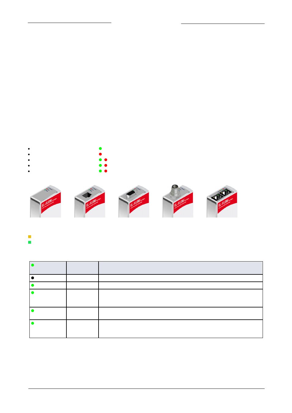
The following LED indicators are present on top of the instrument:
‘Mode’
LED: green
used for operation mode indication
‘Error’
LED: red
used for error/warning messages
‘NET’
LED: green/red
/
used for Network status (DeviceNet™ only)
‘MOD’
LED: green/red
/
used for Module status (DeviceNet™ only)
‘Status’
LED: green/red
/
used for status indication (EtherCAT® and PROFINET only)
Examples:
Analog and RS232 FLOW-BUS and Modbus PROFIBUS DeviceNet™ EtherCAT® and PROFINET
For EtherCAT® and PROFINET the following LED indicators are integrated in the RJ-45 connectors:
Amber LED: Ethernet Speed indicator
Green LED: Ethernet Link/Activity indicator
The tables below list the possible indications by the LEDs on top of the instrument:
green 'Mode'
LED
Time
Indication
Off
Continuous
Power-off or program not running
On
Continuous
Normal Operation Mode
Short flash
0.1 sec on,
2 sec off
Valve Safe State Mode There is no bus communication (PROFIBUS DP, DeviceNet
TM
,
EtherCAT® and PROFINET only). Valves are in safe state. This LED indication is also active
when the instrument is in ‘Initialization Mode' (Init Reset = '73')
Normal flash
0.2 sec on,
0.2 sec off
Special Function Mode The instrument is busy performing a special function, e.g. auto-
zero or self-test
Long flash
2 sec on,
0.1 sec off
Configuration Mode The instrument is in configuration mode. In the configuration
mode the baud rate and bus type for the 9-pin sub-D side connector are set to 38k4 and
RS232 FLOW-BUS (Propar)
Green LED indications