Basic alarm and counter settings, Zeroing (using digital operation), Instrument parameter list – Bronkhorst EL-FLOW Prestige User Manual
Page 29: 4 basic alarm and counter settings, 5 zeroing (using digital operation), 6 instrument parameter list
Bronkhorst High-Tech B.V.
EL-FLOW Prestige
29
9.17.084
3.9.4
Basic alarm and counter settings
The alarm and counter settings are most easily accessible via FlowPlot or FlowView software or any of the
Bronkhorst readout/control units (BRIGHT, E-8000). For more information about the alarm parameters see section
4.2.4, for the counter parameters see section 4.2.5.
3.9.5
Zeroing (using digital operation)
The auto-zero function is most easily accessible via FlowPlot software. Select 'Instrument Settings' and use the 'Auto
zero' button in the 'Basic' tab.
To start the auto-zero function by digital operation use the following procedure:
1. Set parameter ‘
12
Control Mode’ to value 9 (Calibration Mode); the green LED will flash normally (0.2 sec on, 0.2 sec off)
2. Set parameter ‘
58
Calibration Mode’ to value 9 (Auto-zero)
3. The auto-zero function has started
4. Check parameter ‘
58
Calibration Mode’:
o
value 0 = idle (auto-zeroing succeeded), ‘
12
Control Mode’ is set to previous value.
o
value 9 = auto-zero active
o
value 255 = error: restart auto-zero (step 2), ‘
12
Control Mode’ is set to previous value.
3.9.6
Instrument parameter list
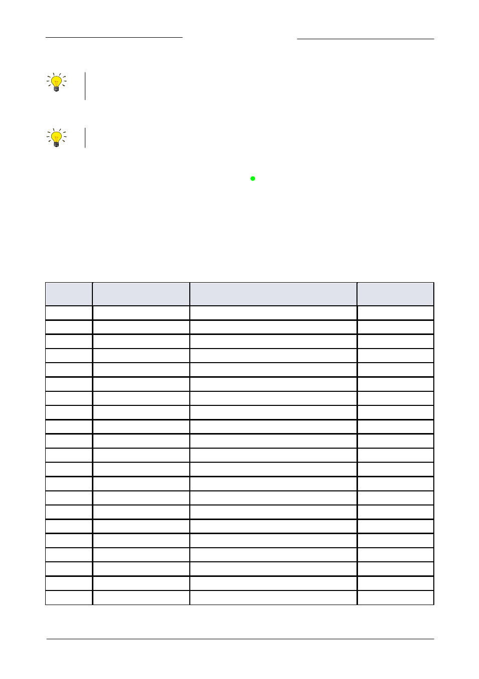
The table below lists the relevant parameters for the EL-FLOW Prestige, sorted by FlowDDE parameter number.
FlowDDE
parameter
Parameter name
Purpose
Section
1
Wink
Special instrument parameter
Section 4.2.2
7
Init Reset
Special instrument parameter
Section 4.2.2
8
Measured Value (Measure)
Measurement/control
Section 3.9.2
9
Setpoint
Measurement/control
Section 3.9.2
11
Analog Input
Measurement/control
Section 4.2.1
12
Control Mode
Special instrument parameter
Section 4.2.2
21
Capacity
Fluidset property
Section 4.2.3
22
Sensor Type
Special instrument parameter
Section 4.2.1
24
Fluid Number
Fluidset property
Section 4.2.3
25
Fluid Name
Fluidset property
Section 4.2.3
28
Alarm Info
Alarm settings
Section 4.2.4
55
Valve Output
Measurement/control
Section 4.2.1
58
Calibration Mode
Special instrument parameter
Section 3.9.5
86
IOStatus
Special instrument parameter
Section 4.4.2
90
Device Type
Diagnostics
Section 5.1
91
BHT Model Number
Identification
Section 3.9.3
92
Serial Number
Identification
Section 3.9.3
93
Customer Model
Identification
Section 3.9.3
105
Firmware Version
Diagnostics
Section 5.1
114
Reset
Special instrument parameter
Section 4.2.2
115
User Tag
Identification
Section 3.9.3