Analog operation, Hook-up, Basic rs232 operation – Bronkhorst EL-FLOW Prestige User Manual
Page 16: 3 analog operation, 4 basic rs232 operation
Bronkhorst High-Tech B.V.
EL-FLOW Prestige
9.17.084
16
3.3
Analog operation
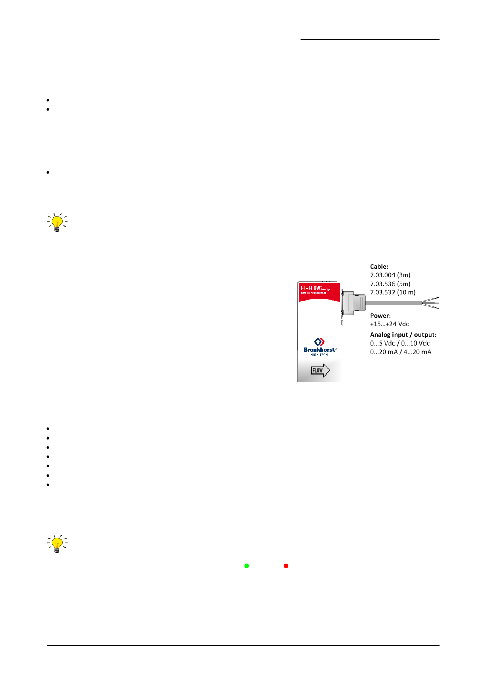
The following analog signals are available for each instrument through the 9-pin sub-D side connector:
Measured value (analog output) at pin 2
Setpoint (analog input/setpoint) at pin 3
The factory selected analog interface (0…5 Vdc; 0…10 Vdc; 0…20 mA or 4…20 mA) can be found in the model key of the instrument
(section 1.5) and in the pin description at the instrument backside label.
Pin 5 is used for customized I/O configurations. However, by default it is set as an analog output:
Valve output (control signal only) 0…10 Vdc at pin 5 (default)
For customized pin 5 I/O configurations see section 4.4.1. The factory selected pin 5 configuration can be found in the model key of
the instrument (section 1.5) and in the pin description at the instrument backside label.
When operating the instrument through the analog interface it is possible to connect the instrument simultaneously
to RS232 for reading/changing parameters (e.g. settings or fluid selection).
3.3.1
Hook-up
Refer to the hook-up diagram for analog operation (document 9.16.119)
or use a 9-pin sub-D loose-end cable to connect the required signals.
3.4
Basic RS232 operation
Digital RS232 (or bus) operation adds a lot of extra features to the instruments compared to analog operation, such as:
Up to eight selectable and customizable fluids (section 3.1.1)
Multi gas / multi range functionality (section 3.1.1)
Direct reading at readout/control module or host computer (section 3.4.1)
Self-testing and diagnostics (section 5.1)
Identification (section 3.9.3)
Adjustable minimum and maximum alarm limits (section 3.9.4)
(Batch) counter (section 3.9.4)
Each instrument process is controlled (internally) by specific parameters. The instrument parameter values are accessible through
the available digital interfaces to influence the instrument behavior. In this section it is explained how to operate an instrument
using RS232 communication.
Make sure that the instrument back-side label indicates RS232 settings for the 9-pin sub-D connector and apply the
proper Baud rate settings. If the instrument is not set for RS232 communication, use the micro switch on top of the
instrument to overrule the custom settings and switch to RS232 communication settings: press and hold the micro
switch at power-up and wait (12…16 sec) until both green and red LEDs flash (0.2 sec on, 0.2 sec off). Release
the switch to activate the ‘Configuration Mode’. In the ‘Configuration Mode’ the bus type and baud rate for the 9-pin
sub-D side connector are set to RS232 FLOW-BUS (Propar) at 38400 Baud. The ‘Configuration Mode’ remains active
after power down. Use the same procedure to deactivate the ‘Configuration Mode’.