Micro switch functions, 8 micro switch functions – Bronkhorst EL-FLOW Prestige User Manual
Page 26
Bronkhorst High-Tech B.V.
EL-FLOW Prestige
9.17.084
26
3.8
Micro switch functions
By means of manual operation of the micro push-button switch some important actions for the instrument can be selected or
started. These options are available in both analog and digital operation mode. These functions are:
Reset alarm
Reset instrument (firmware program reset)
Auto-zero
Restore factory settings (in case of accidentally changing of the settings)
Activate 'Configuration Mode' (for changing communication settings via RS232)
Using digital RS485 operation via the 9-pin sub-D side connector it is also possible to read/set:
Bus-address (node-address) (only required for RS485)
The micro switch on top of the EL-FLOW Prestige can be operated with a thin, metal or hard plastic pin, for example
the end of a paperclip.
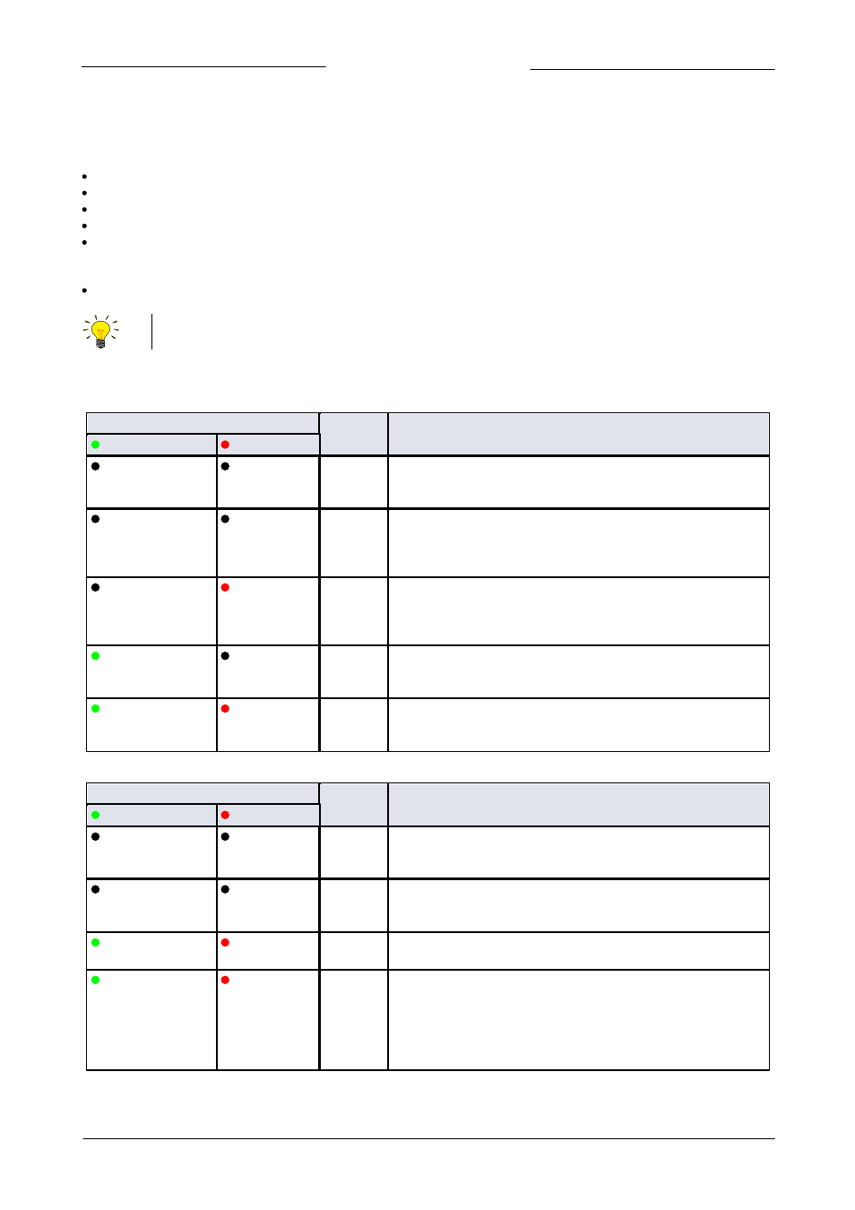
When the micro switch is pressed, both LEDs will start indicating different patterns in a loop. The switch has to be pressed down
until the two LEDs are indicating the right pattern. When the switch is released, the selected action is started. The tables below
describe the micro switch functions that can be started in normal operation mode and during power-up:
LEDs
Time
pushed
Indication
green ‘Mode’ LED
red ‘Error’ LED
Off
Off
0…1 sec.
No action
Pressing a switch briefly by accident will not start any unwanted
reaction of the instrument.
Off
Off
1…4 sec.
In case of min/max alarm or counter batch reached: Reset alarm
(only if reset by micro switch has been enabled).
For FLOW-BUS only: if the node address is occupied, this function
will install a free node-address on FLOW-BUS.
Off
On (red)
4…8 sec.
Reset instrument
Instrument program will be restarted and all warning and error
messages will be cleared. During start-up the instrument will
perform a (new) self-test.
On (green)
Off
8…12 sec.
Auto-zero
Instrument will be re-adjusted for measurement of zero-flow, see
section 2.9.
On (green)
On (red)
12…16
sec.
Prepare instrument for FLASH mode for firmware update.
Instrument shuts down and both LEDs turn off. At next power-up the
instrument will be active again.
LED indications using micro switch at normal operation mode of an instrument
LEDs
Time
pushed
Indication
green ‘Mode’ LED
red ‘Error’ LED
Off
Off
0…4 sec.
No action
Pressing a switch briefly by accident will not start any unwanted
reaction of the instrument.
Off
Normal flash
0.2 sec on,
0.2 sec off
4…8 sec.
Restore factory settings
All parameter settings (except field bus/communication settings) will
be restored to the original factory settings.
Normal flash
0.2 sec on, 0.2 sec off
On (red)
8…12 sec.
For FLOW-BUS only: install a free node-address on FLOW-BUS.
Normal flash
0.2 sec on, 0.2 sec off
Normal flash
0.2 sec on,
0.2 sec off
12…16
sec.
Activate ‘Configuration Mode’
The baud rate and bus type for the 9-pin sub-D side connector are
set to 38k4 and RS232 FLOW-BUS (Propar). The ‘Configuration Mode’
is recognized by the green LED blinking 2 sec on, 0.1 sec off. The
‘Configuration Mode’ is deactivated only after applying this micro
switch action again.
LED indications using micro switch at power-up situation of an instrument