Hook-up, 1 hook-up – Bronkhorst EL-FLOW Prestige User Manual
Page 21
Bronkhorst High-Tech B.V.
EL-FLOW Prestige
21
9.17.084
3.5.1
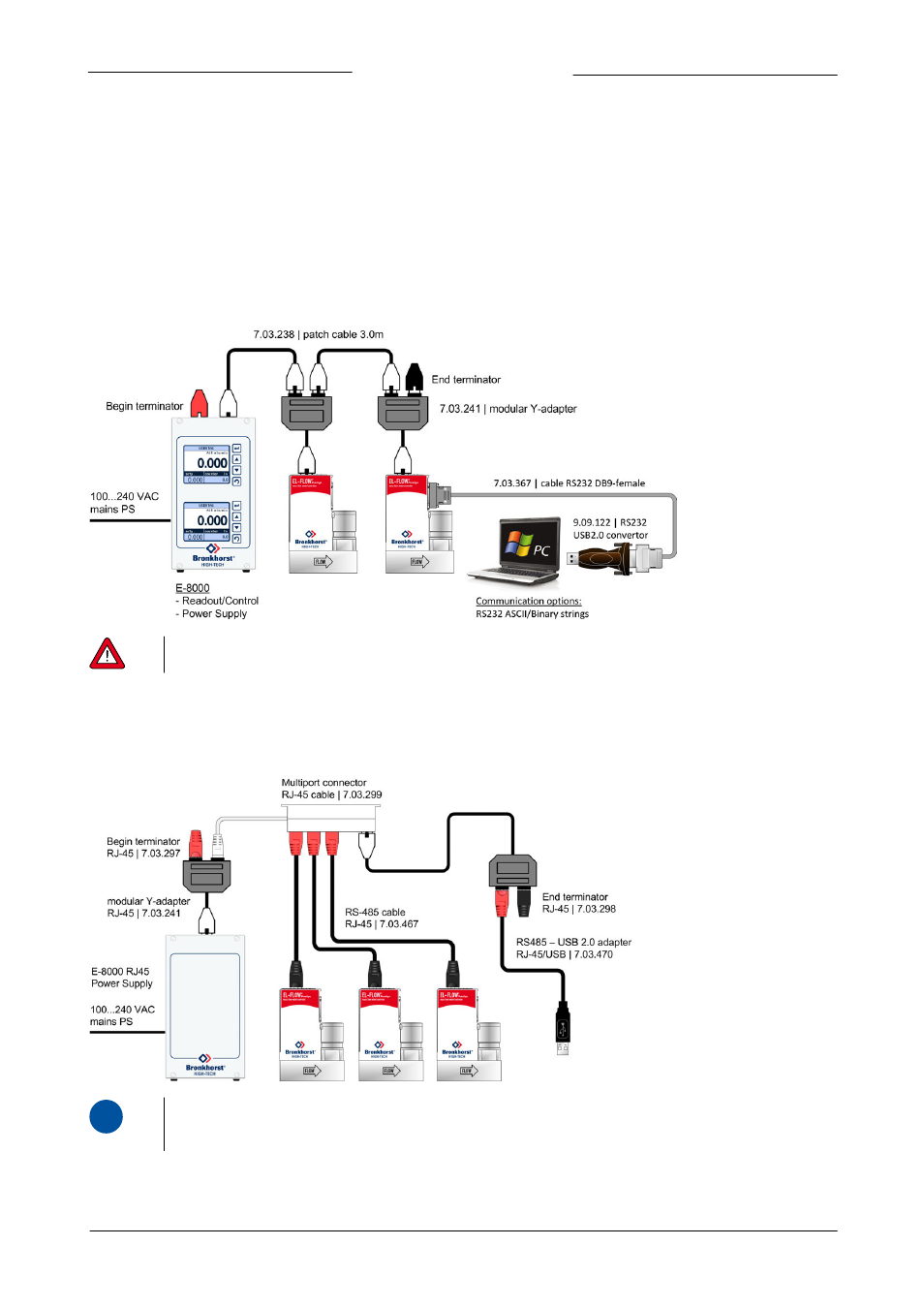
Hook-up
The illustrations below show examples of a number of EL-FLOW Prestige instruments in an RS485 bus-system. Note that many
other bus configurations are possible, contact your local sales representative for more information. Please check the total power
consumption of your instruments and do not exceed the maximum power of the power supply.
FLOW-BUS setup (example)
In the example below an E-8000 power supply/readout control unit with FLOW-BUS is connected to two EL-FLOW Prestige
instruments via the RJ-45 top-connector FLOW-BUS interface. In this example one instrument serves as 'local host' for
communicating with a pc to all instruments on the bus via an available RS232 connector. Note: communication with all the
instruments on the FLOW-BUS system is possible when using an EL-FLOW Prestige instrument as local-host RS232/FLOW-BUS
interface. It is also possible to use multiple local-host RS232/FLOW-BUS interfaces in a FLOW-BUS system simultaneously.
Power the instruments in a FLOW-BUS local-host system by hooking-up the power supply directly on the FLOW-BUS
line and not by powering a set of instruments through the 9-pin sub-D connector on one of the digital instruments.
Modbus setup (example)
In the example below the Modbus power supply is provided by an E-8000. The EL-FLOW Prestige instruments are connected to the
bus via RS485 cables with RJ-45 connector and a Multiport connector. The RS485 - USB2.0 adapter can be used to connect the
system to a Modbus master device.
i
www
For possible power supply and communication options, refer to document 9.17.076 'Instruction manual E-8000 PS /
readout and control module':