Bronkhorst EL-FLOW Prestige User Manual
Page 44
Bronkhorst High-Tech B.V.
EL-FLOW Prestige
9.17.084
44
When the controller output is used for pump or external valve steering (Mass Flow Meters only), make sure the
‘
231
Valve Maximum’ is set to 0.3 [A]. For Mass Flow Controllers, the controller output is limited to a value below
10 Vdc due to the maximum valve current restriction.
C3A
Digital output, min/max alarm
During a min/max alarm, pin 5 is pulled down to 0 Vdc.
C4A
Digital output, counter alarm
During a counter alarm, pin 5 is pulled down to 0 Vdc.
C5S
Digital output, enabled by setpoint (for shut-off control)
Pin 5 is pulled down to 0 Vdc at a controller setpoint, e.g. for shut-off valve activation.
For factory selected analog control (…-A#-C5S):
When the ‘
12
Control Mode’ is set for analog control by factory, the minimum setpoint at which the device (shut-
off valve) connected to pin 5 is activated is 1.9%, to avoid that possible noise on the analog input does accidentally
activate the device.
For factory selected digital control (…-D#-C5S):
When the ‘
12
Control Mode’ is set for digital control by factory, the setpoint threshold for activating the device
connected to pin 5 is any value > 0.
Note: If the instrument is forced into ‘Valve Safe State’, the digital output is not affected, so a (n.c.) shut-off valve
connected to pin 5 will not close when the (n.c.) controller is in ‘Valve Safe State’.
Make sure to use 24Vdc power supply corresponding to the shut-off valve specifications. Cable 7.03.572 (T-part 9-
pin D-sub/loose end) or 7.03.603 (T-part 9-pin D-sub/DIN43650C) can be used for this operating option.
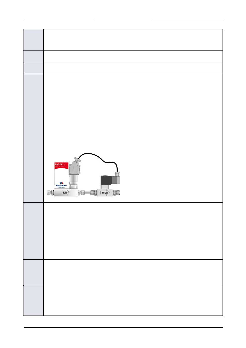
Example for -C5S- or -C0I- hook-up
C0I
Digital output, high/low switch via remote parameter (for shut-off control)
Pin 5 is pulled down to 0 Vdc when writing value 1 to parameter ‘
288
IO Switch Status’, this is undone by writing
value 0.
A device connected to pin5 (e.g. a shut-off valve) can be activated/de-activated by writing the parameter ‘
288
IO
Switch Status’.
Note: If the instrument is forced into ‘Valve Safe State’, the digital output is also affected, so a (n.c.) shut-off valve
connected to pin 5 will be closed when the (n.c.) controller is in ‘Valve Safe State’.
Make sure to use 24Vdc power supply corresponding to the shut-off valve specifications. Cable 7.03.572 (T-part 9-
pin D-sub/loose end) or 7.03.603 (T-part 9-pin D-sub/DIN43650C) can be used for this operating option.
D9E
Digital frequency output, measure
Measurement value is translated to a frequency within given frequency range.
The default frequency range to represent 0…100% flow is 0…10000 Hz. Any other frequency range must be
specified on order.
F9B
Digital pulse output, batch counter
Pin 5 is pulled down to 0 Vdc when a given batch size is reached (during a given pulse length).
By default, a pulse is given at each 1x the ‘
128
Counter Unit’ batch value, with a pulse length of 1 s. For instance,
when the ‘
128
Counter Unit’ is set to l
n
, a pulse is given each time 1 l
n
has passed through the instrument. An