Advanced alarm parameters, 4 advanced alarm parameters – Bronkhorst EL-FLOW Prestige User Manual
Page 39
Bronkhorst High-Tech B.V.
EL-FLOW Prestige
39
9.17.084
4.2.4
Advanced alarm parameters
Bronkhorst digital instruments have a built-in alarm function. It is used to indicate several types of alarm:
System errors
System warnings
Min/max alarms
Response alarms
Batch alarm
Master/slave alarms
The alarm types can be set with the parameter ‘
118
Alarm Mode’. When an alarm occurs, the type of alarm can be read out using
parameter ‘
28
Alarm Info’. After an alarm, an automatic setpoint change can be set using the parameters ‘
120
Alarm Setpoint Mode’
and ‘
121
Alarm New Setpoint’. It is also possible to set an alarm delay to prevent overreaction to small disturbances using the
parameter ‘
182
Alarm Delay Time’. How an alarm can be reset is controlled by the parameter ‘
156
Reset Alarm Enable’. It can bit-wise
be set to automatic, reset, external or keyboard/micro switch. Note: when an alarm is disabled, it will only switch off after the set
‘
156
Alarm Delay Time’ has passed.
Alarm Mode
Type
Access
Range
FlowDDE
FLOW-BUS
Modbus
Unsigned char
RW
0...3
118
97/3
0x0C23/3108
Available alarm modes:
Value 0: Alarm off
Value 1: Alarm on absolute limits
Value 2: Alarm on limits related to setpoint (response alarm)
Value 3: Alarm when instrument powers-up (e.g. after power-down)
For DeviceNet
TM
only modes 0 and 1 are available.
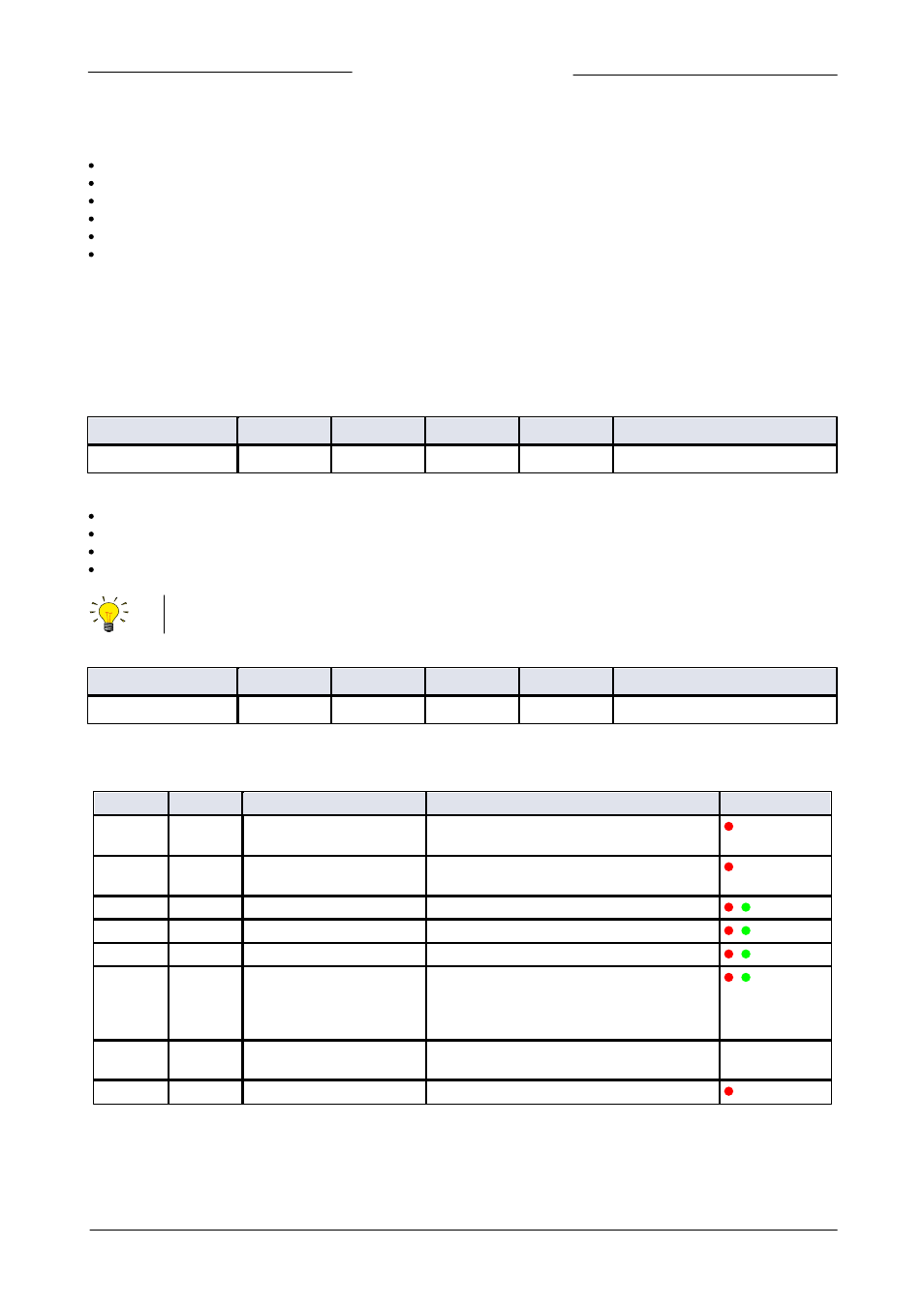
Alarm Info
Type
Access
Range
FlowDDE
FLOW-BUS
Modbus
Unsigned char
R
0…255
28
1/20
0x0034/53
This parameter contains 8 bits with status information about (alarm) events in the instrument (convert value to binary number to
see which bits are active).
Bit
Low (0)
High (1)
Description
LED indication
0
No error
An error occurred
Alarm register 2 contains an error
On (red) /
normal flash
1
No error
A warning occurred
Alarm register 1 contains a warning
On (red) /
normal flash
2
No error
Minimum alarm
‘Measured Value’ < ‘Alarm Minimum Limit’
/ Slow wink
3
No error
Maximum alarm
‘Measured Value’ > ‘Alarm Maximum Limit’
/ Slow wink
4
No error
Batch counter alarm
Batch counter reached its limit
/ Slow wink
5
No error
This bit only:
Together with bit 2 or 3:
Power-up alarm (probably a power dip
occurred)
Response alarm (too much difference between
‘
8
Measured Value’ and ‘
9
Setpoint’)
/ Slow wink
6
No error
Master/slave alarm
'Setpoint' out of limits due to ‘Slave Factor’ (>
100%)
N/A
7
No error
Hardware alarm
Hardware error
On (red)
Alarm events