Fluke Biomedical 956A-201-M2 User Manual
Page 29
3-3
The UDR can be configured to automatically reset the alarm relays and alarm indicators, or it can hold the
alarm relays de-energized and flash the alarm indicators until the alarm acknowledge (ALARM ACK)
pushbutton is pressed. If the ALARM ACK pushbutton is pressed while the alarm condition still exists, the
indicators will go to a steady state, and the relays will remain de-energized until the alarm condition returns
to normal. Upon resumption of normal operation, the relays will energize and alarm indicators will
extinguish. The bargraph color will always indicate the current status; green for normal, amber for warn,
and red for a high alarm.
Front panel pushbuttons labeled HIGH and WARN can be used to display the respective alarm set points.
To drive a local alarm, a 120 Vac is internally wired from alarm output connector P1 to the alarm relay
contact on P2-13 and 14. Refer to Modification Sheet 956A-201-M2MS and Loop Drawing S174014C-
102.
Range Alarm
If the measured radiation field is below the underrange setpoint (minimum range of the detector used), the
front panel display will indicate 0.00 mR/h, the bargraph will indicate the actual radiation value, and the
RANGE alarm indicator will illuminate in red. The minimum range is adjustable by the underrange
setpoint, and is defaulted to 1.00E-1 mR/h. When the measured radiation field increases into the range of
the detector, the RANGE alarm indicator will extinguish and normal operation will begin.
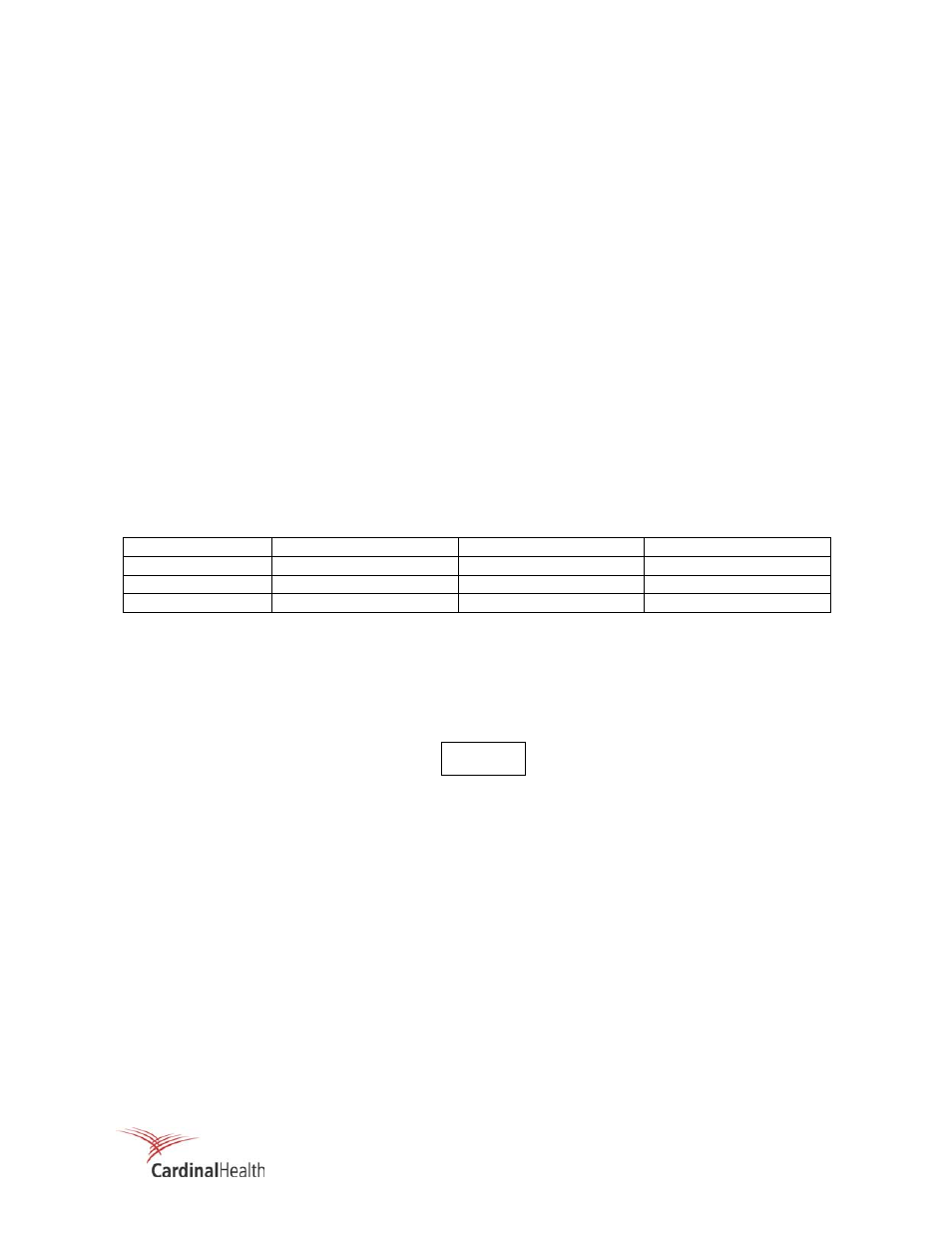
There are three ranges for the ratemeter, one for each detector range (low, medium, & high). The specific
range for each detector is established by operator-entered setpoints (refer to "Setpoint Entry" for actual
entry procedures). The detector range for each specific detector is shown below.
Detector
Detector Range
Underrange Setpoint
Overrange Setpoint
897A-210/211
0.01 to 10E3 mR/h 1.00E-2
1.00E3
897A-220/221
0.1 to 10E4 mR/h 1.00E-1
1.00E4
897A-230/231
1 to 10E5 mR/h 1.00E0
1.00E5
If the measured radiation field goes above the overrange setpoint, the RANGE alarm indicator will
illuminate and the front panel display will indicate EEEEE, the bargraph will illuminate in red, and the
analog output will be set to full scale. The maximum range of the detector used is determined by the
overrange setpoint. When the measured radiation field returns within the maximum operating range of the
detector and the condition is acknowledged, the RANGE alarm indicator will extinguish and normal
operation will resume.
In addition to the display of EEEEE when in Overrange, the
mR/h engineering units will be displayed if the HIGH or WARN
front panel set point display pushbuttons have been accessed.
IF desired, the mR/h units display may be cleared by either
pressing the ENTER push button, or cycling the UDR power
OFF/ON. The mR/h unit’s display, however, does not affect the
operation of the Overrange function.
In the event the detector output exceeds the electronic anti-jam circuit trip level, the anti-jam fuse will open
and the Fail relay will change state to indicate a monitor not in service condition. Replacement of the anti-
jam fuse (F1) will be required in order to return the rate meter to normal operation.
FAIL Alarm
Detector failure, detector overrange, or microprocessor failure are some of the conditions which can
produce a FAIL alarm and in some cases an error display. The Fail condition is true whenever any
equipment failure is detected and false when no equipment failures are detected.
NOTE