Fluke Biomedical 956A-201-M2 User Manual
Page 82
5-4
2.
If any voltage does not meet the tolerance after adjusting the +5.0 Vdc supply, the unit should be
returned to Cardinal Health, Radiation Management Services for replacement of the DC power
supply.
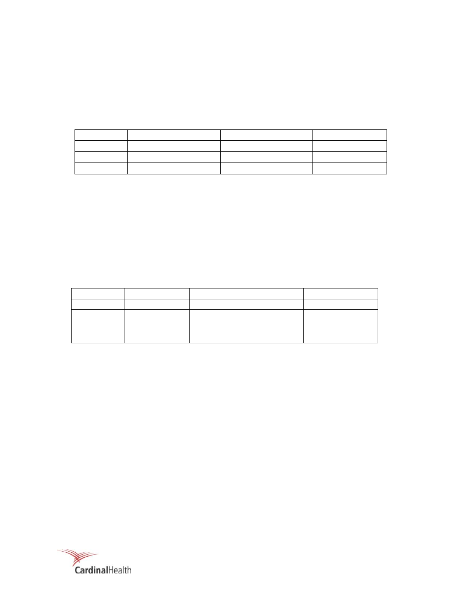
Discriminator Check, 956A-201 UDR
1.
Set the digital voltmeter to DC volts and measure the upper and lower discriminator voltages using
the values listed in Table 5-2.
Table 5-2. Discriminator Test Points
Test Point
Description
Expected Voltage
Potentiometer
GND Ground
N/A
N/A
LO Low
Discriminator
0.5 Vdc
± 0.01 V
VR11
HI High
Discriminator
7.000 Vdc
± 0.01 V
VR10
2.
If either voltage is out of tolerance, it may be brought into tolerance by adjusting the appropriate
potentiometer.
3.
If the proper adjustments cannot be achieved, return the unit to Cardinal Health, Radiation
Management Services for repair.
High Voltage Check, 956A-201 UDR
1. With the digital voltmeter set to read DC voltage, measure the detector high voltage as listed in Table
5-3.
Table 5-3. High Voltage Test Points
Test Point
Description
Expected Voltage
Potentiometer
GND Ground N/A
N/A
HV Test
HV, 1000:1
897A-210 0.575 V
± .01 Vdc
897A-220 0.575 V
± .01 Vdc
897A-230 0.550 V
± .01 Vdc
R5
R5
R5
2. If the 1000:1 voltage is out of tolerance, adjust R5 as required.
3. If the proper HV adjustment cannot be achieved, return the unit to Cardinal Health, Radiation
Management Services for repair.
Analog Output Check, 956A-201 UDR
1. To adjust the low scale output, enter 1.00E2 (a value greater than the background reading) into
setpoint 7, Analog Low Scale setpoint.
2. Adjust the appropriate zero adjust potentiometer as listed in Table 5-4 as required. The output signals
may be measured at the terminals as listed in Table 5-5.