Fluke Biomedical 956A-201-M2 User Manual
Page 90
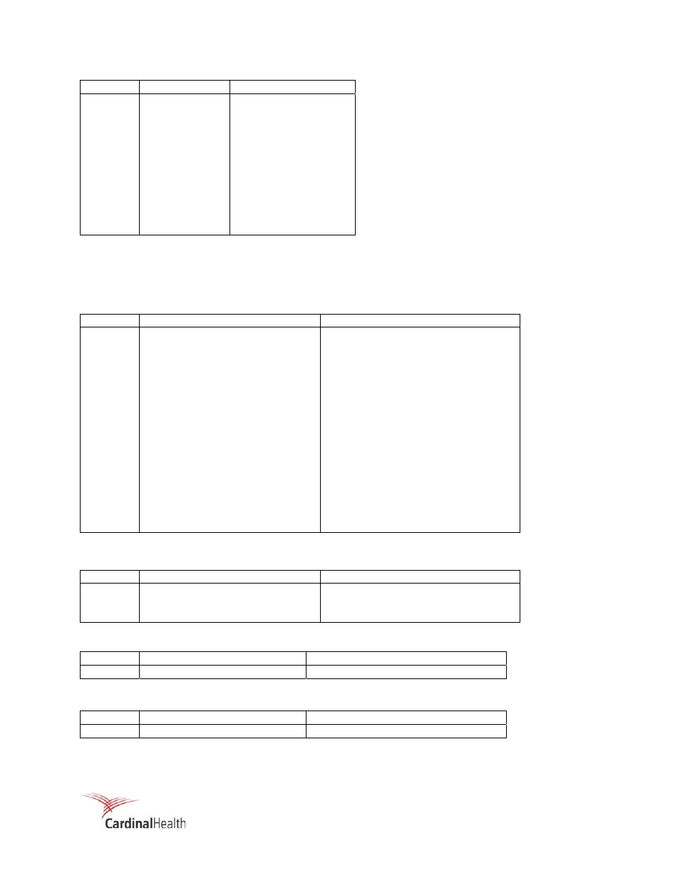
A-2
Pin Signal
Internal
Connection
27 Spare
Not
Used
28 Spare
Not
Used
29 Spare
Not
Used
30 Spare
Not
Used
31 Spare
Not
Used
32 Spare
Not
Used
33 Spare
Not
Used
34 Spare
Not
Used
35 Spare
Not
Used
36 Spare
Not
Used
37 Spare
Not
Used
n.o. = normally open
n.c. = normally closed
Relay contacts are shown in their shelf, or de-energized state.
Table A-3. Connector P2 – Detector Connector, 956A-201-M2
Pin Signal
Internal
Connection
1
Detector + 15 Vdc Supply
Power Supply +15 Vdc
2
Not Used
Power Supply -15 Vdc
3
Supply Ground
Power Supply Ground
4
+ 15 V C/S On
Relay K2
5
+ 15 V C/S Off
Relay K2
6 Not
Used
-
7 Not
Used
-
8 Not
Used
-
9
DC Ground
Main Circuit Board J5-9
10
* 0 – 10 Vdc, Remote Meter
Main Circuit Board J5-10
11
AC Ground
P1-3, AC Ground
12
Fail, N.C. (Switched 120 Vac
Line)
Relay Board, K1-C (Line)
13
120 VAC (Neutral)
P1-2 120 VAC (N)
14
Alarm N.C. (Switched 120 Vac
Line)
Relay Board K5-E (L)
*0 – 10 Vdc selected for Remote Meter use on P2 (10, 11) not P6 (5, 6).
Table A-4. Connector P3 – Power Input
Pin Signal
Internal
Connection
1
120 VAC – Line
Line Fuse (F2)
2
120 VAC – Neutral
Power Supply 120 Vac (n)
3 Safety
Ground
Chassis
Table A-5. Connector P4 – Detector High Voltage
Pin Signal
Internal
Connection
MHV
Detector High Voltage
Direct
Table A-6. Connector P5 – Detector Signal Input
Pin Signal
Internal
Connection
BNC Detector
Signal
Direct